Chapter: Civil : Construction Planning And Scheduling
Civil: The Critical Path Method

The
Critical Path Method
The most widely used scheduling technique is the
critical path method (CPM) for scheduling, often referred to as critical path
scheduling. This method calculates the minimum completion time for a project
along with the possible start and finish times for the project activities.
Indeed, many texts and managers regard critical path scheduling as the only
usable and practical scheduling procedure. Computer programs and algorithms for
critical path scheduling are widely available and can efficiently handle
projects with thousands of activities.
The critical path itself represents the set or
sequence of predecessor/successor activities which will take the longest time
to complete. The duration of the critical path is the sum of the activities'
durations along the path. Thus, the critical path can be defined as the longest
possible path through the "network" of project activities, as
described in Chapter 9. The duration of the critical path represents the
minimum time required to complete a project. Any delays along the critical path
would imply that additional time would be required to complete the project.
There may be more than one critical path among all
the project activities, so completion of the entire project could be delayed by
delaying activities along any one of the critical paths. For example, a project
consisting of two activities performed in parallel that each require three days
would have each activity critical for a completion in three days.
Formally, critical path scheduling assumes that a
project has been divided into activities of fixed duration and well defined
predecessor relationships. A predecessor relationship implies that one activity
must come before another in the schedule. No resource constraints other than
those implied by precedence relationships are recognized in the simplest form
of critical path scheduling.
To use
critical path scheduling in practice, construction planners often represent a
resource constraint by a precedence relation. A constraint is simply a
restriction on the options available to a manager, and a resource constraint is
a constraint deriving from the limited availability of some resource of
equipment, material, space or labor. For example, one of two activities
requiring the same piece of equipment might be arbitrarily assumed to precede
the other activity. This artificial precedence constraint insures that the two
activities requiring the same resource will not be scheduled at the same time.
Also, most critical path scheduling algorithms impose restrictions on the
generality of the activity relationships or network geometries which are used.
In essence, these restrictions imply that the construction plan can be
represented by a network plan in which activities appear as nodes in a network,
as in Figure 1-6. Nodes are numbered, and no two nodes can have the same number
or designation. Two nodes are introduced to represent the start and completion
of the project itself.
The actual computer representation of the project
schedule generally consists of a list of activities along with their associated
durations, required resources and predecessor activities. Graphical network
representations rather than a list are helpful for visualization of the plan
and to insure that mathematical requirements are met. The actual input of the
data to a computer program may be accomplished by filling in blanks on a screen
menu, reading an existing data file, or typing data directly to the program
with identifiers for the type of information being provided.
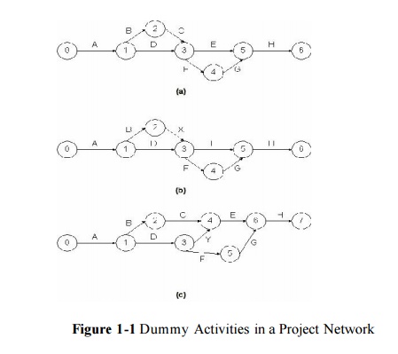
With an
activity-on-branch network, dummy activities may be introduced for the purposes
of providing unique activity designations and maintaining the correct sequence
of activities. A dummy activity is assumed to have no time duration and can be
graphically represented by a dashed line in a network. Several cases in which
dummy activities are useful are illustrated in Fig. 10-1. In Fig. 10-1(a), the
elimination of activity C would mean that both activities B and D would be
identified as being between nodes 1 and 3. However, if a dummy activity X is
introduced, as shown in part (b) of the figure, the unique designations for
activity B (node 1 to 2) and D (node 1 to 3) will be preserved. Furthermore, if
the problem in part (a) is changed so that activity E cannot start until both C
and D are completed but that F can start after D alone is completed, the order
in the new sequence can be indicated by the addition of a dummy activity Y, as
shown in part (c). In general, dummy activities may be necessary to meet the
requirements of specific computer scheduling algorithms, but it is important to
limit the number of such dummy link insertions to the extent possible.

Many
computer scheduling systems support only one network representation, either
activity-on-branch or activity-on-node. A good project manager is familiar with
either representation.
Related Topics