Chapter: Digital Signal Processing : Signals and System
Basic Block Diagram of A/D Converter
BASIC BLOCK DIAGRAM OF A/D
CONVERTER
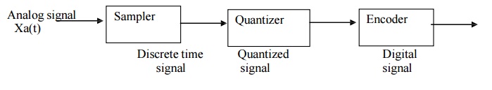
SAMPLING THEOREM
It is the
process of converting continuous time signal into a discrete time signal by
taking samples of the continuous time signal at discrete time instants.
X[n]=
Xa(t) where t= nTs = n/Fs ….(1)
When
sampling at a rate of fs samples/sec, if k is any positive or negative integer,
we cannot distinguish between the samples values of fa Hz and a sine wave of
(fa+ kfs) Hz. Thus (fa + kfs) wave is alias or image of a wave.
Thus Sampling Theorem states that if the
highest frequency in an analog signal is Fmax and the signal is sampled at the
rate fs > 2Fmax then x(t) can be exactly recovered from its sample values.
This sampling rate is called Nyquist rate of sampling. The imaging or aliasing
starts after Fs/2 hence folding frequency is fs/2. If the frequency is less
than or equal to 1/2 it will be represented properly.
Thus the
frequency 50 Hz, 90 Hz , 130 Hz … are alias of the frequency 10 Hz at the
sampling rate of 40 samples/sec
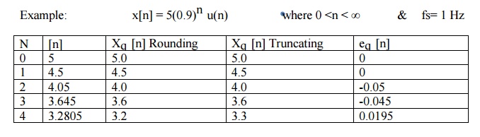
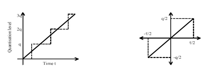
QUANTIZATION
The
process of converting a discrete time continuous amplitude signal into a
digital signal by expressing each sample value as a finite number of digits is
called quantization. The error introduced in representing the continuous values
signal by a finite set of discrete value levels is called quantization error or
quantization noise.
Quantization
Step/Resolution : The difference between the two quantization levels is called
quantization step. It is given by ∆ = XMax – xMin / L-1 where L indicates
Number of quantization levels.
CODING/ENCODING
Each
quantization level is assigned a unique binary code. In the encoding operation,
the quantization sample value is converted to the binary equivalent of that
quantization level.
If 16
quantization levels are present, 4 bits are required. Thus bits required in the
coder is the smallest integer greater than or equal to Log2 L. i.e b= Log2 L
Thus Sampling frequency is calculated as fs=Bit rate / b.
ANTI-ALIASING FILTER
When
processing the analog signal using DSP system, it is sampled at some rate
depending upon the bandwidth. For example if speech signal is to be processed
the frequencies upon 3khz can be used. Hence the sampling rate of 6khz can be
used. But the speech signal also contains some frequency components more than
3khz. Hence a sampling rate of 6khz will introduce aliasing. Hence signal
should be band limited to avoid aliasing.
The
signal can be band limited by passing it through a filter (LPF) which blocks or
attenuates all the frequency components outside the specific bandwidth. Hence
called as Anti aliasing filter or pre-filter. (Block Diagram)
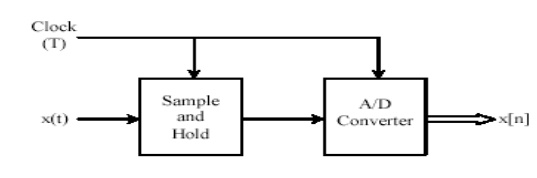
SAMPLE-AND-HOLD CIRCUIT:
The
sampling of an analogue continuous-time signal is normally implemented using a
device called an analogue-to- digital converter (A/D). The continuous-time
signal is first passed through a device called a sample-and-hold (S/H) whose
function is to measure the input signal value at the clock instant and hold it
fixed for a time interval long enough for the A/D operation to complete.
Analogue-to-digital conversion is potentially a slow operation, and a variation
of the input voltage during the conversion may disrupt the operation of the
converter. The S/H prevents such disruption by keeping the input voltage
constant during the conversion. This is schematically illustrated by Figure.
After a
continuous-time signal has been through the A/D converter, the quantized output
may differ from the input value. The maximum possible output value after the
quantization process could be up to half the quantization level q above or q
below the ideal output value. This deviation from the ideal output value is
called the quantization error. In order to reduce this effect, we increases the
number of bits.
Q) Calculate Nyquist Rate for the
analog signal x(t)
1) x(t)=
4 cos 50 ∏t + 8 sin 300∏t –cos 100∏t Fn=300
Hz
2) x(t)=
2 cos 2000∏t+ 3 sin 6000∏t + 8 cos 12000∏t Fn=12KHz
3) x(t)=
4 cos 100∏t Fn=100
Hz
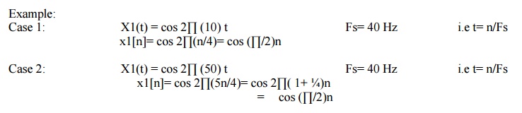
Q) The following four analog
sinusoidal are sampled with the fs=40Hz. Find out corresponding time signals and comment on them
X1(t)=
cos 2∏(10)t
X2(t)=
cos 2∏(50)t
X3(t)=
cos 2∏(90)t
X4(t)=
cos 2∏(130)t
Q) Signal x1(t)=10cos2∏(1000)t+ 5
cos2∏(5000)t. Determine Nyquist rate. If the signal is sampled at 4khz will the signal be recovered from its samples.
Q) Signal x1(t)=3 cos 600∏t+
2cos800∏t. The link is operated at 10000 bits/sec and each input sample is quantized into 1024
different levels. Determine Nyquist rate, sampling frequency, folding frequency
& resolution.
DIFFERENCE BETWEEN FIR AND IIR
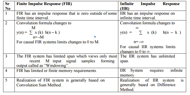
Discrete
time systems has one more type of classification.
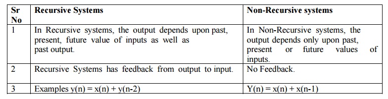
a)
Recursive Systems
b) Non-Recursive
Systems
Related Topics