Chapter: Physics : Effects of electric current : Higher Secondary(12 Std)
Alternating current
Alternating current
As we have seen earlier a rotating coil in a magnetic field, induces an alternating emf and hence an alternating current. Since the emf induced in the coil varies in magnitude and direction periodically, it is called an alternating emf. The significance of an alternating emf is that it can be changed to lower or higher voltages conveniently and efficiently using a transformer. Also the frequency of the induced emf can be altered by changing the speed of the coil. This enables us to utilize the whole range of electromagnetic spectrum for one purpose or the other. For example domestic power in India is supplied at a frequency of 50 Hz. For transmission of audio and video signals, the required frequency range of radio waves is between 100 KHz and 100 MHz. Thus owing to its wide applicability most of the countries in the world use alternating current.
1. Measurement of AC
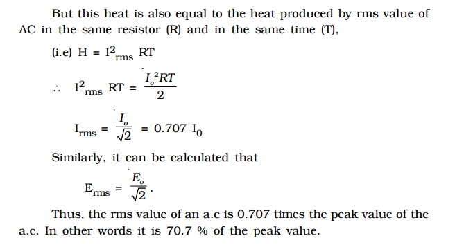
Since alternating current varies continuously with time, its average value over one complete cycle is zero. Hence its effect is measured by rms value of a.c.
RMS value of a.c.
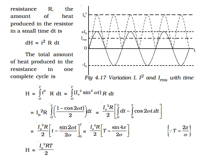
The rms value of alternating current is defined as that value of the steady current, which when passed through a resistor for a given time, will generate the same amount of heat as generated by an alternating current when passed through the same resistor for the same time.
The rms value is also called effective value of an a.c. and is denoted by Irms or Ieff.
when an alter-nating current i=Io sin ωt flows through a resistor of
2. AC Circuit with resistor
Let an alternating source of emf be connected across a resistor of resistance R.
The instantaneous value of the applied emf is
e = Eo sin ωt . . .(1)
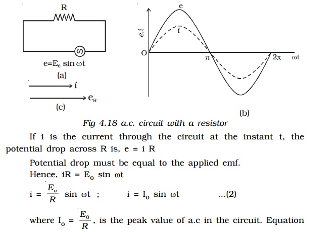
(2) gives the instantaneous value of current in the circuit containing R. From the expressions of voltage and current given by equations (1) and
(2) it is evident that in a resistive circuit, the applied voltage and current are in phase with each other (Fig 4.18b).
Fig 4.18c is the phasor diagram representing the phase relationship between the current and the voltage.
3. AC Circuit with an inductor
Let an alternating source of emf be applied to a pure inductor of inductance L. The inductor has a negligible resistance and is wound on a laminated iron core. Due to an alternating emf that is applied to the inductive coil, a self induced emf is generated which opposes the applied voltage. (eg) Choke coil.
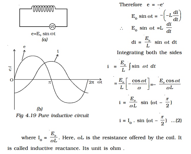
From equations (1) and (2) it is clear that in an a.c. circuit containing a pure inductor the current i lags behind the voltage e by the phase angle of π/2.
Conversely the voltage across L leads the current by the phase angle of π/2. This fact is presented graphically in Fig 4.19b.
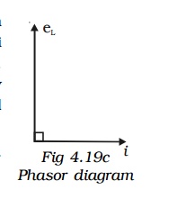
Fig 4.19c represents the phasor diagram of a.c. circuit containing only L.
Inductive reactance
XL = ωL = 2πν L, where ν is the frequency of the a.c. supply
For d.c. ν = 0; ∴ XL = 0
Thus a pure inductor offers zero resistance to d.c. But in an a.c. circuit the reactance of the coil increases with increase in frequency.
4. AC Circuit with a capacitor
An alternating source of emf is connected across a capacitor of capacitance C (Fig 4.20a). It is charged first in one direction and then in the other direction.
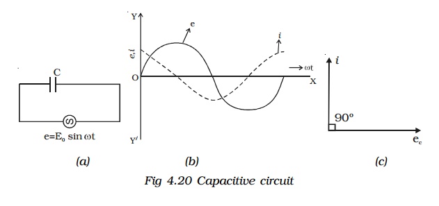
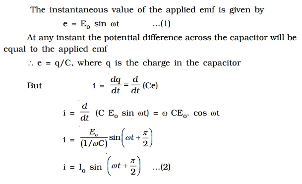
From equations (1) and (2), it follows that in an a.c. circuit with a capacitor, the current leads the voltage by a phase angle of π/2. In otherwords the emf lags behind the current by a phase angle of π/2. This is represented graphically in Fig 4.20b.
Fig 4.20c represents the phasor diagram of a.c. circuit containing only C.
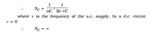
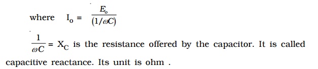
Thus a capacitor offers infinite resistance to d.c. For an a.c. the capacitive reactance varies inversely as the frequency of a.c. and also inversely as the capacitance of the capacitor.
5. Resistor, inductor and capacitor in series
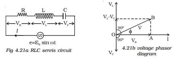
Let an alternating source of emf e be connected to a series combination of a resistor of resistance R, inductor of inductance L and a capacitor of capacitance C (Fig 4.21a).
Let the current flowing through the circuit be I.
The voltage drop across the resistor is, VR = I R (This is in phase with I)
The voltage across the inductor coil is VL = I XL (VL leads I by π/2)
The voltage across the capacitor is, VC = IXC (VC lags behind I by π/2)
The voltages across the different components are represented in the voltage phasor diagram (Fig. 4.21b).
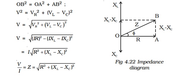
VL and VC are 180o out of phase with each other and the resultant of VL and VC is (VL – VC), assuming the circuit to be predominantly inductive. The applied voltage ‘V’ equals the vector sum of VR, VL and VC.
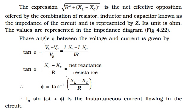
Series resonance or voltage resonance in RLC circuit
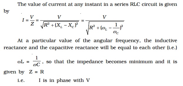
The particular frequency νo at which the impedance of the circuit becomes minimum and therefore the current becomes maximum is called Resonant frequency of the circuit. Such a circuit which admits maximum current is called series resonant circuit or acceptor circuit. Thus the maximum current through the circuit at resonance is

Maximum current flows through the circuit, since the impedance of the circuit is merely equal to the ohmic resistance of the circuit. i.e Z = R
Acceptor circuit
The series resonant circuit is often called an ‘acceptor’ circuit. By offering minimum impedance to current at the resonant frequency it is able to select or accept most readily this particular frequency among many frequencies.
In radio receivers the resonant frequency of the circuit is tuned to the frequency of the signal desired to be detected. This is usually done by varying the capacitance of a capacitor.
Q-factor
The selectivity or sharpness of a resonant circuit is measured by the quality factor or Q factor. In other words it refers to the sharpness of tuning at resonance.
The Q factor of a series resonant circuit is defined as the ratio of the voltage across a coil or capacitor to the applied voltage.
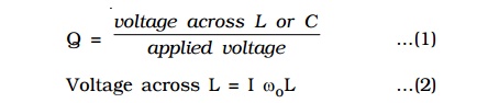
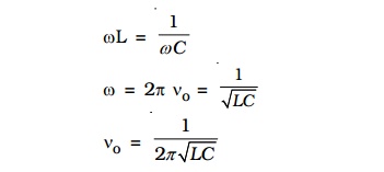
where ωo is the angular frequency of the a.c. at resonance.
The applied voltage at resonance is the potential drop across R, because the potential drop across L is equal to the drop across C and they are 180o out of phase. Therefore they cancel out and only potential drop across R will exist.
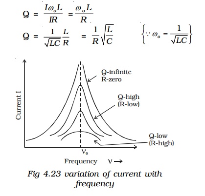
Q is just a number having values between 10 to 100 for normal frequencies. Circuit with high Q values would respond to a very narrow frequency range and vice versa. Thus a circuit with a high Q value is sharply tuned while one with a low Q has a flat resonance. Q-factor can be increased by having a coil of large inductance but of small ohmic resistance.
Current frequency curve is quite flat for large values of resistance and becomes more sharp as the value of resistance decreases. The curve shown in Fig 4.23 is also called the frequency response curve.
6. Power in an ac circuit
In an a.c circuit the current and emf vary continuously with time. Therefore power at a given instant of time is calculated and then its mean is taken over a complete cycle. Thus, we define instantaneous power of an a.c. circuit as the product of the instantaneous emf and the instantaneous current flowing through it.
The instantaneous value of emf and current is given by
e = Eo sin ωt
i = Io sin (ωt + φ)
where φ is the phase difference between the emf and current in an a.c circuit
The average power consumed over one complete cycle is
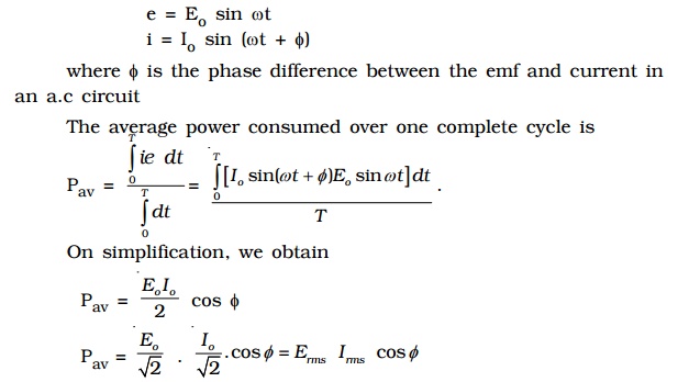
Pav = apparent power × power factor
where Apparent power = Erms Irms and power factor = cos φ
The average power of an ac circuit is also called the true power of the circuit.
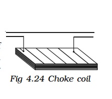
Choke coil
A choke coil is an inductance coil of very small resistance used for controlling current in an a.c. circuit. If a resistance is used to control current, there is wastage of power due to Joule heating effect in the resistance. On the other hand there is no dissipation of power when a current flows through a pure inductor.
Construction
It consists of a large number of turns of insulated copper wire wound over a soft iron core. A laminated core is used to minimise eddy current loss (Fig. 4.24).
Working
The inductive reactance offered by the coil is given by
∴ The average power consumed by the choke coil over a complete cycle is
Pav = Erms Irms cos π/2 = 0
However in practice, a choke coil of inductance L possesses a small resistance r. Hence it may be treated as a series combination of an inductor and small resistance r. In that case the average power consumed by the choke coil over a complete cycle is
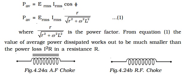
Chokes used in low frequency a.c. circuit have an iron core so that the inductance may be high. These chokes are known as audio – frequency (A.F) chokes. For radio frequencies, air chokes are used since a low inductance is sufficient. These are called radio frequency (R. F) or high frequency (H.F) chokes and are used in wireless receiver circuits (Fig. 4.24a and Fig. 4.24b).
Choke coils can be commonly seen in fluorescent tubes which work on alternating currents.
Related Topics