Chapter: Physics : Effects of electric current : Higher Secondary(12 Std)
Electromagnetic induction
Electromagnetic Induction and Alternating Current
In the year 1820, Hans Christian Oersted demonstrated that a current carrying conductor is associated with a magnetic field. Thereafter, attempts were made by many to verify the reverse effect of producing an induced emf by the effect of magnetic field.
Electromagnetic induction
Michael Faraday demonstrated the reverse effect of Oersted experiment. He explained the possibility of producing emf across the ends of a conductor when the magnetic flux linked with the conductor changes. This was termed as electromagnetic induction. The discovery of this phenomenon brought about a revolution in the field of power generation.
1. Magnetic flux
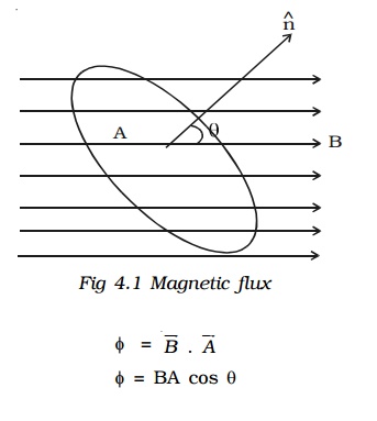
The magnetic flux (φ) linked with a surface held in a magnetic field (B) is defined as the number of magnetic lines of force crossing a closed area (A) (Fig 4.1). If θ is the angle between the direction of the field and normal to the area, then

2. Induced emf and current – Electromagnetic induction.
Whenever there is a change in the magnetic flux linked with a closed circuit an emf is produced. This emf is known as the induced emf and the current that flows in the closed circuit is called induced current. The phenomenon of producing an induced emf due to the changes in the magnetic flux associated with a closed circuit is known as electromagnetic induction.

Faraday discovered the electromagnetic induction by conducting several experiments.
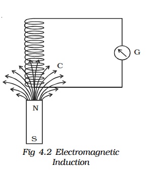
Fig 4.2 consists of a cylindrical coil C made up of several turns of insulated copper wire connected in series to a sensitive galvanometer G. A strong bar magnet NS with its north pole pointing towards the coil is moved up and down. The following inferences were made by Faraday.
(i) Whenever there is a relative motion between the coil and the magnet, the galvanometer shows deflection indicating the flow of induced current.
(ii) The deflection is momentary. It lasts so long as there is relative motion between the coil and the magnet.
(iii) The direction of the flow of current changes if the magnet is moved towards and withdrawn from it.
(iv) The deflection is more when the magnet is moved faster, and less when the magnet is moved slowly.
(v) However, on reversing the magnet (i.e) south pole pointing towards the coil, same results are obtained, but current flows in the opposite direction.

Faraday demonstrated the electromagnetic induction by another experiment also.
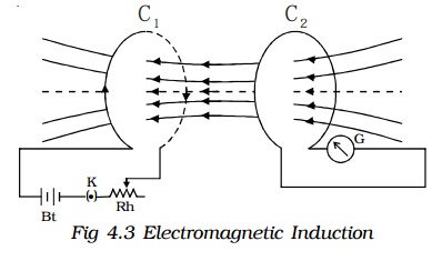
Fig 4.3 shows two coils C1 and C2 placed close to each other.
The coil C1 is connected to a battery Bt through a key K and a rheostat. Coil C2 is connected to a sensitive galvanometer G and kept close to C1. When the key K is pressed, the galvanometer connected with the coil C2 shows a sudden momentary deflection. This indicates that a current is induced in coil C2. This is because when the current in C1 increases from zero to a certain steady value, the magnetic flux linked with the coil C1 increases. Hence, the magnetic flux linked with the coil C2 also increases. This causes the deflection in the galvanometer.
On releasing K, the galvanometer shows deflection in the opposite direction. This indicates that a current is again induced in the coil C2. This is because when the current in C1 decreases from maximum to zero value, the magnetic flux linked with the coil C1 decreases. Hence, the magnetic flux linked with the coil C2 also decreases. This causes the deflection in the galvanometer in the opposite direction.
3. Faraday’s laws of electromagnetic induction
Based on his studies on the phenomenon of electromagnetic induction, Faraday proposed the following two laws.
First law
Whenever the amount of magnetic flux linked with a closed circuit changes, an emf is induced in the circuit. The induced emf lasts so long as the change in magnetic flux continues.
Second law
The magnitude of emf induced in a closed circuit is directly proportional to the rate of change of magnetic flux linked with the circuit.
Let φ1 be the magnetic flux linked with the coil initially and φ2 be the magnetic flux linked with the coil after a time t. Then

4. Lenz’s law
The Russian scientist H.F. Lenz in 1835 discovered a simple law giving the direction of the induced current produced in a circuit. Lenz’s law states that the induced current produced in a circuit always flows in such a direction that it opposes the change or cause that produces it.
If the coil has N number of turns and φ is the magnetic flux linked with each turn of the coil then, the total magnetic flux linked with the coil at any time is Nφ

Lenz’s law - a consequence of conservation of energy
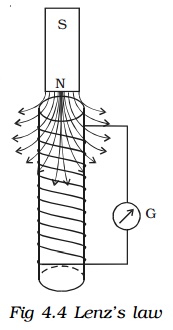
Copper coils are wound on a cylindrical cardboard and the two ends of the coil are connected to a sensitive galvanometer. A magnet is moved towards the coil (Fig 4.4). The upper face of the coil acquires north polarity.

Consequently work has to be done to move the magnet further against the force of repulsion. When we withdraw the magnet away from the coil, its upper face acquires south polarity. Now the workdone is against the force of attraction. When the magnet is moved, the number of magnetic lines of force linking the coil changes, which causes an induced current to flow through the coil. The direction of the induced current, according to Lenz’s law is always to oppose the motion of the magnet. The workdone in moving the magnet is converted into electrical energy. This energy is dissipated as heat energy in the coil. If on the contrary, the direction of the current were to help the motion of the magnet, it would start moving faster increasing the change of magnetic flux linking the coil. This results in the increase of induced current. Hence kinetic energy and electrical energy would be produced without any external work being done, but this is impossible. Therefore, the induced current always flows in such a direction to oppose the cause. Thus it is proved that Lenz’s law is the consequence of conservation of energy.
5. Fleming’s right hand rule
The forefinger, the middle finger and the thumb of the right hand are held in the three mutually perpendicular directions. If the forefinger points along the direction of the magnetic field and the thumb is along the direction of motion of the conductor, then the middle finger points in the direction of the induced current. This rule is also called generator rule.
Related Topics