Chapter: Physics : Effects of electric current : Higher Secondary(12 Std)
AC generator (Dynamo) - Single phase
AC generator (Dynamo) – Single phase
The ac generator is a device used for converting mechanical energy into electrical energy. The generator was originally designed by a Yugoslav scientist Nikola Tesla.
Principle
It is based on the principle of electromagnetic induction, according to which an emf is induced in a coil when it is rotated in a uniform magnetic field.
Essential parts of an AC generator
(i) Armature
Armature is a rectangular coil consisting of a large number of loops or turns of insulated copper wire wound over a laminated soft iron core or ring. The soft iron core not only increases the magnetic flux but also serves as a support for the coil
(ii) Field magnets
The necessary magnetic field is provided by permanent magnets in the case of low power dynamos. For high power dynamos, field is provided by electro magnet. Armature rotates between the magnetic poles such that the axis of rotation is perpendicular to the magnetic field.
(iii) Slip rings
The ends of the armature coil are connected to two hollow metallic rings R1 and R2 called slip rings. These rings are fixed to a shaft, to which the armature is also fixed. When the shaft rotates, the slip rings along with the armature also rotate.
(iv) Brushes
B1 and B2 are two flexible metallic plates or carbon brushes. They provide contact with the slip rings by keeping themselves pressed against the ring. They are used to pass on the current from the armature to the external power line through the slip rings.
Working
Whenever, there is a change in orientation of the coil, the magnetic flux linked with the coil changes, producing an induced emf in the coil. The direction of the induced current is given by Fleming’s right hand rule.
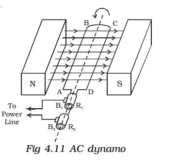
Suppose the armature ABCD is initially in the vertical position. It is rotated in the anticlockwise direction. The side AB of the coil moves downwards and the side DC moves upwards (Fig. 4.11). Then according to Flemings right hand rule the current induced in arm AB flows from B to A and in CD it flows from D to C. Thus the current flows along DCBA in the coil. In the external circuit the current flows from B1 to B2.
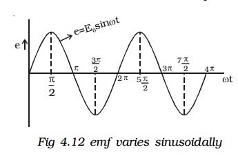
On further rotation, the arm AB of the coil moves upwards and DC moves downwards. Now the current in the coil flows along ABCD. In the external circuit the current flows from B2 to B1. As the rotation of the coil continues, the induced current in the external circuit keeps changing its direction for every half a rotation of the coil. Hence the induced current is alternating in nature (Fig 4.12). As the armature completes ν rotations in one second, alternating current of frequency ν cycles per second is produced. The induced emf at any instant is given by e= Eo sin ωt
The peak value of the emf, Eo = NBAω
where N is the number of turns of the coil,
A is the area enclosed by the coil,
B is the magnetic field and
ω is the angular velocity of the coil
1. AC generator (Alternator) – Three phase
A single phase a.c. generator or alternator has only one armature winding. If a number of armature windings are used in the alternator it is known as polyphase alternator. It produces voltage waves equal to the number of windings or phases. Thus a polyphase system consists of a numerous windings which are placed on the same axis but displaced from one another by equal angle which depends on the number of phases. Three phase alternators are widely preferred for transmitting large amount of power with less cost and high efficiency.
Generation of three phase emf
In a three – phase a.c. generator three coils are fastened rigidly together and displaced from each other by 120o. It is made to rotate about a fixed axis in a uniform magnetic field. Each coil is provided with a separate set of slip rings and brushes.
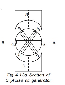
An emf is induced in each of the coils with a phase difference of 120o. Three coils a1 a2, b1 b2 and c1 c2 are mounted on the same axis but displaced from each other by 120o, and the coils rotate in the anticlockwise direction in a magnetic field (Fig 4.13a).
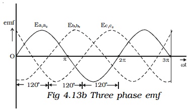
When the coil a1a2 is in position AB, emf induced in this coil is zero and starts increasing in the positive direction. At the same instant the coil b1b2 is 120o behind coil a1 a2, so that emf induced in this coil is approaching its maximum negative value and the coil c1 c2 is 240o behind the coil a1 a2, so the emf induced in this coil has passed its positive maximum value and is decreasing. Thus the emfs induced in all the three coils are equal in magnitude and of same frequency. The emfs induced in the three coils are ;
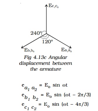
The emfs induced and phase difference in the three coils a1 a2, b1 b2 and c1 c2 are shown in Fig 4.13b & Fig 4.13c.
Related Topics