Chapter: Mechanical : Robotics : Robot Drive Systems and End Effectors
DC Servo Motors | Stepper Motor

DC Servo Motors | Stepper Motor
Under Electrical Motor
As we know that any electrical motor can be utilized as servo motor if it is controlled by
servomechanism. Likewise, if we control a
DC motor by means of servomechanism, it would be referred as DC servo
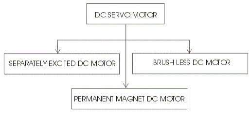
motor. There are different types of
DC motor, such shunt wound DC motor, series DC motor,
Separately excited DC motor,
permanent magnet DC motor,
Brushless DC motor etc. Among all mainly separately excited DC motor, permanent
magnet DC motor and brush less DC motor are used as servo.
DC Servo Motor
The motors which are
utilized as DC servo motors, generally have separate DC source for field
winding and armature winding. The control can be archived either by controlling
the field current or armature current.
Field control has some specific advantages over armature control and on the
other hand armature control has also some specific advantages over field
control. Which type of control should be applied to the DC servo motor, is
being decided depending upon its specific applications. Let's discus DC servo
motor working principle for field control and armature control one by one.
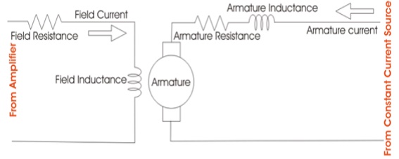
Field Controlled DC Servo Motor
The figure below illustrates
the schematic diagram for a field controlled DC servo motor. In this
arrangement the field of DC motor is
excited be the amplified error signal and armature winding is energized by a
constant current source .
The field is controlled below
the knee point of magnetizing saturation curve. At that portion of the curve
the mmf linearly varies with excitation current. That means torque developed in
the DC motor is directly proportional to
the field current below the knee point
of magnetizing saturation curve From general
torque equation of DC motor it is found that, torque T ∝φIa. Where, φ isaarmaturefieldcurrent.
fluxButinfield controlledand IDC servo motor, the armature is excited by
constant current source , hence Ia is
constan.
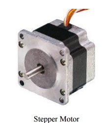
The DC Stepper Motor
Like the DC motor above,
Stepper Motors are also electromechanical actuators that convert a pulsed
digital input signal into a discrete (incremental) mechanical movement are used
widely in industrial control applications. A stepper motor is a type of
synchronous brushless motor in that it does not have an armature with a
commutator and carbon brushes but has a rotor made up of many, some types have
hundreds of permanent magnetic teeth and a stator with individual windings.
As it name implies, the
stepper motor does not rotate in a continuous fashion like
a conventional DC motor
but moves in discret rotational movement or step dependant upon the number of
stator poles and rotor teeth the stepper motor has.
Because of their discrete
step operation, stepper motors can easily be rotated a finite fraction of a
rotation at a time, such as 1.8, 3.6, 7.5 degrees etc. So for example, lets
assume that a stepper motor completes one full revolution (360o in exactly 100
steps.
Then the step angle for
the motor is given as 360 degrees/100 steps = 3.6 degrees per step. This value
is commonly known as the stepper motors Step Angle.
There are three basic
types of stepper motor, Variable Reluctance, Permanent Magnet andHybrid (a sort
of combination of both). A Stepper Motor is particularly well suited to
applications that require accurate positioning and repeatability with a fast
response to starting, stopping, reversing and speed control and another key
feature of the stepper motor, is its ability to hold the load steady once the
require position is achieved.
Generally, stepper motors
have an internal rotor with a large number of permanent h”magnetwith
“teetanumber of electromagnet stators electromagnets are polarized and
depolarized sequentially, causing the rotor to rotate one
“step” at a time.
Modern multi-pole,
multi-teeth stepper motors are capable of accuracies of less than 0.9 degs per
step (400 Pulses per Revolution) and are mainly used for highly accurate
positioning systems like those used for magnetic-heads in floppy/hard disc
drives, printers/plotters or robotic applications. The most commonly used
stepper motor being the 200 step per revolution stepper motor. It has a 50
teeth rotor, 4-phase stator and a step angle of 1.8 degrees (360 degs/(50×4)).
Stepper Motor Construction and Control
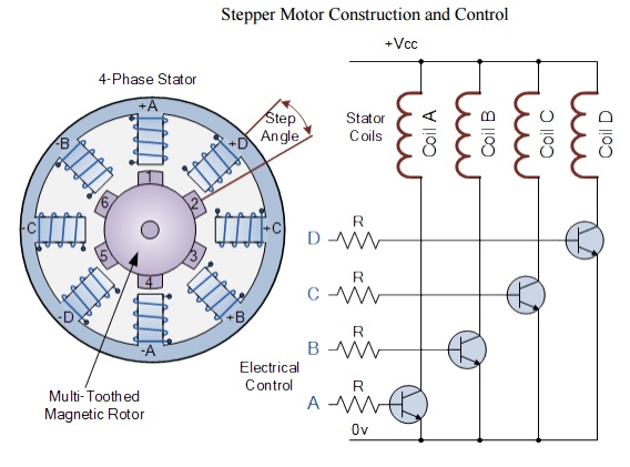
In our simple example of a
variable reluctance stepper motor above, the motor consists of a central rotor
surrounded by four electromagnetic field coils labelled A, B, C and D.
All the
coils with the same
letter are connected together so
that energising, say
coils marked A will cause the magnetic rotor to align itself with that
set of coils.
By applying power to each
set of coils in turn the rotor can be made to rotate or "step" from
one position to the next by an angle determined by its step angle construction,
and by energising the coils in sequence the rotor will produce a rotary motion.
The stepper motor driver
controls both the step angle and speed of the motor by energising the field
coilsADCB,in ADCB,aset”ADCB,setc,quencAth… rotor will rotate in one direction
(forward) and by reversing the pulseABCD, seq ABCD, ABCD,”etc,A… the rotor will
rotate in the
So in our simple example
above, the stepper motor has four coils, making it a 4-phase motor, with the
number of poles on the stator being eight (2 x 4) which are spaced at 45 degree
intervals. The number of teeth on the rotor is six which are spaced 60 degrees
apart.
Then there are 24 (6 teeth
x 4 coils) complete one full revolution. Therefore, the step angle above is
given as: 360o/24 = 15o.
Obviously, the more rotor
teeth and or stator coils would result in more control and a finer step angle.
Also by connecting the electrical coils of the motor in different
configurations, Full, Half and micro-step angles are possible. However, to
achieve micro-stepping, the stepper motor must be driven by a (quasi)
sinusoidal current that is expensive to implement.
It is also possible to
control the speed of rotation of a stepper motor by altering the time delay
between the digital pulses applied to the coils (the frequency), the longer the
delay the slower the speed for one complete revolution. By applying a fixed
number of pulses to the motor, the motor shaft will rotate through a given
angle.
The advantage of using
time delayed pulse is that there would be no need for any form of additional
feedback because by counting the number of pulses given to the motor the final
position of the rotor will be exactly known. This response to a set number of
digital input pulses allows the stepper motor to operate i cheaper to control.
Related Topics