Chapter: Physics : Effects of electric current : Higher Secondary(12 Std)
Transformer
Transformer
Transformer is an electrical device used for converting low alternating voltage into high alternating voltage and vice versa. It transfers electric power from one circuit to another. The transformer is based on the principle of electromagnetic induction.

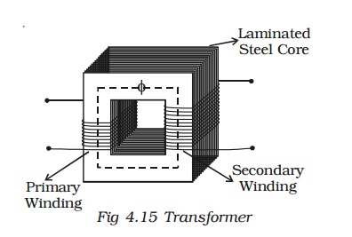
A transformer consists of primary and secondary coils insulated from each other, wound on a soft iron core (Fig 4.15). To minimise eddy currents a laminated iron core is used. The a.c. input is applied across the primary coil. The continuously varying current in the primary coil produces a varying magnetic flux in the primary coil, which in turn produces a varying magnetic flux in the secondary. Hence, an induced emf is produced across the secondary.
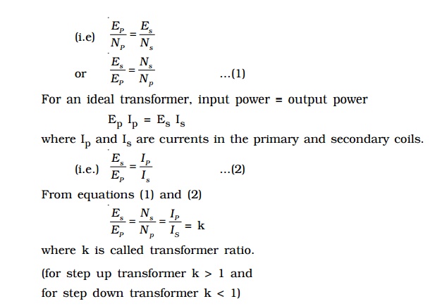
Let EP and ES be the induced emf in the primary and secondary coils and NP and NS be the number of turns in the primary and secondary coils respectively. Since same flux links with the primary and secondary, the emf induced per turn of the two coils must be the same

In a step up transformer Es > Ep implying that Is < Ip. Thus a step up transformer increases the voltage by decreasing the current, which is in accordance with the law of conservation of energy. Similarly a step down transformer decreases the voltage by increasing the current.
Efficiency of a transformer
Efficiency of a transformer is defined as the ratio of output power to the input power.

The efficiency η = 1 (ie. 100%), only for an ideal transformer where there is no power loss. But practically there are numerous factors leading to energy loss in a transformer and hence the efficiency is always less than one.
Energy losses in a transformer
(1) Hysteresis loss
The repeated magnetisation and demagnetisation of the iron core caused by the alternating input current, produces loss in energy called hysterisis loss. This loss can be minimised by using a core with a material having the least hysterisis loss. Alloys like mumetal and silicon steel are used to reduce hysterisis loss.
(2) Copper loss
The current flowing through the primary and secondary windings lead to Joule heating effect. Hence some energy is lost in the form of heat. Thick wires with considerably low resistance are used to minimise this loss.
(3) Eddy current loss (Iron loss)
The varying magnetic flux produces eddy current in the core. This leads to the wastage of energy in the form of heat. This loss is minimised by using a laminated core made of stelloy, an alloy of steel.
(4) Flux loss
The flux produced in the primary coil is not completely linked with the secondary coil due to leakage. This results in the loss of energy. This loss can be minimised by using a shell type core.
In addition to the above losses, due to the vibration of the core, sound is produced, which causes a loss in the energy.
1. Long distance power transmission
The electric power generated in a power station situated in a remote place is transmitted to different regions for domestic and industrial use. For long distance transmission, power lines are made of conducting material like aluminium. There is always some power loss associated with these lines.

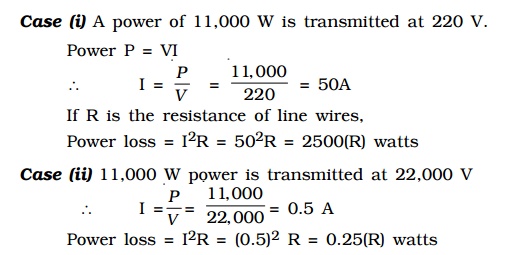
If I is the current through the wire and R the resistance, a considerable amount of electric power I2R is dissipated as heat. Hence, the power at the receiving end will be much lesser than the actual power generated. However, by transmitting the electrical energy at a higher voltage, the power loss can be controlled as is evident from the following two cases.
Case (i) A power of 11,000 W is transmitted at 220 V.
Power P = VI

Power loss = I2R = (0.5)2 R = 0.25(R) watts
Hence it is evident that if power is trasmitted at a higher voltage the loss of energy in the form of heat can be considerably reduced.
For transmitting electric power at 11,000 W at 220 V the current capacity of line wires has to be 50 A and if transmission is done at 22,000 V, it is only 0.5 A. Thus, for carrying larger current (50A) thick wires have to be used. This increases the cost of transmission. To support these thick wires, stronger poles have to be erected which further adds on to the cost. On the other hand if transmission is done at high voltages, the wires required are of lower current carrying capacity. So thicker wires can be replaced by thin wires, thus reducing the cost of transmission considerably.
For example, 400MW power produced at 15,000 V in the power station at Neyveli, is stepped up by a step-up transformer to 230,000 V before transmission. The power is then transmitted through the transmission lines which forms a part of the grid. The grid connects different parts of the country. Outside the city, the power is stepped down to 110,000 V by a step-down transformer. Again the power is stepped down to 11,000 V by a transformer. Before distribution to the user, the power is stepped down to 230 V or 440 V depending upon the need of the user.
Related Topics