Chapter: Civil : Principles of Solid Mechanics : Slip Line Analysis
Solutions for Weightless MohrCoulomb Materials
Solutions for Weightless MohrCoulomb
Materials
When there is a
frictional component of shear strength (i.e., ŽĢ> 0), but no body forces (╬│=0), we have shown in Section 12.6 that for uniform surface loadings the
slip lines or ŌĆ£characteristicsŌĆØ must be straight or log spirals. For wedges
then, the combined failure mechanism will be similar to that for EPS material,
but with the circular portion replaced by a logspiral fan as in Figure 12.15.
We could now work our way along the slip surface from the known boundary point at C on BC to the unknown boundary point A on BA using the solution [Equation (12.20)] to K├ČtterŌĆÖs equation for ╬│=0. Just as for the previous case for a heavy EPS with ŽĢ=0, this shooting technique would give a solution dependent on the extent of zone II (the angle Žł) which, in turn, is related to the angle of wall friction. Unfortunately this general development and the resulting expressions are complicated and cumbersome. For example, even if we assume a
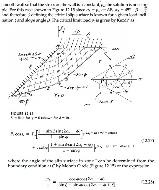
Let us instead work out
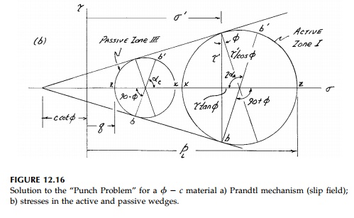
the specific case of the classic punch or strip footing problem shown in Figure
12.16. If pL is the major principal stress and slip sur face
for the active wedge (zone I) must be at
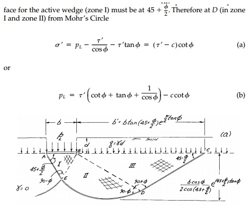
But since D is
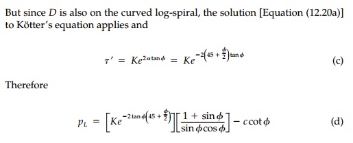
also on the curved logspiral, the solution [Equation (12.20a)] to K├ČtterŌĆÖs
equation applies and
The same procedure can
now be used at point E, which is on the logspiral fan and wedge III. In
this case
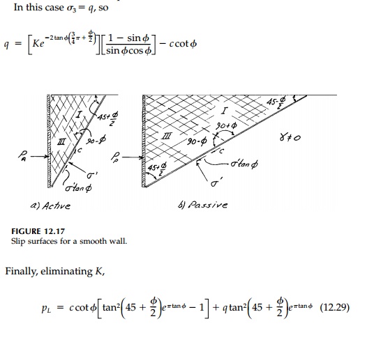
which is the classic result derived by Prandtl* in 1920 for the punch problem for a weightless material. For foundations, q is the depth of burial, d, so q =╬│d and the formula is written
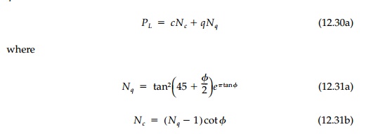
As a final example,
consider the case of a vertical retaining wall. If the wall is smooth, the
normal stress on it is principal and the Coulomb solution, Equation (12.3) or
(12.5), must be correct since zone II disappears (Figure 12.17) and the slip
surface is straight. It is important to note that when the slip lines are
straight it is not necessary to assume the material weightless since ╬▒ is a constant and K├ČtterŌĆÖs equation can be integrated directly giving the
Coulomb solution.
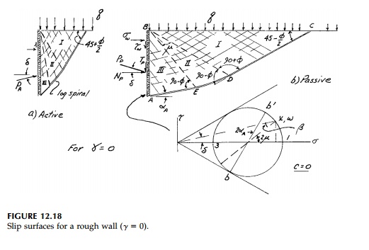
However, if the wall is rough ( ╬┤> 0) we must assume ╬│= 0 to integrate along the logspiral portion of the slip surfaces for either the active or passive cases as shown in Figure 12.18. It will turn out that the effect of roughness is not very significant for the active case while it is very important for passive failure. Therefore, let us solve the passive case and leave the active case for a chapter problem. To simplify the situation further, let us assume that c = 0.
The stresses on the
wall are constant so that at any depth the MohrŌĆÖs Circle is as shown in Figure
12.18. Therefore

where ┬Ą is the angle
from the x axis to the major principal stress. But it can be shown from
MohrŌĆÖs circle (Figure 12.18) that

so that ┬Ą, which is the
change in angle from D to E as we move along the logspiral fan,
can be found in terms of any angle of wall friction. Since we now know the
critical shear stress on the slip surface at D and E, we can
proceed as before to apply K├ČtterŌĆÖs equation to determine that

Total forces on the
wall Np and Tp necessary to reach the
passive limit state are then these stresses times the height of the wall.
Related Topics