Chapter: Civil : Principles of Solid Mechanics : Slip Line Analysis
Retaining Wall Solution for (EPS Material)
Retaining Wall Solution for (EPS Material)
First let us consider a wedge as shown in Figure
12.9 where for simplicity we will assume the top surface, BC, is free of
boundary tractions and there is a rigid retaining wall supporting the EPS
material with unit weight ╬│ on the sloping face
AB. If the wall moves outward in the direction of the v arrows, the
active state of limiting equilibrium develops. A general failure surface, which
by our analysis is a combination of straight and circular segments, is assumed.
This is a combination of an upper wedge (slip field I) with plane surfaces of
sliding, a circular transition section, II, and a third wedge, III, adjoining
the wall.
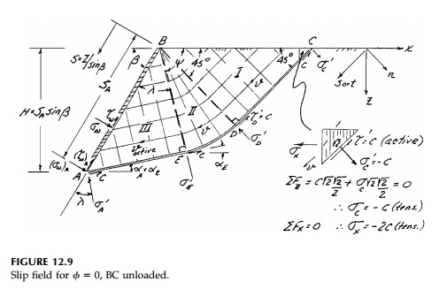
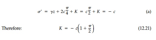
Since we do not know the extent of slip fields II and III or the stresses on the wall, we cannot solve directly but must work our way along the slip surface* from the known boundary, BC, to the unknown boundary, AB, using the solution [Equation (12.15)] to K├ČtterŌĆÖs equation for ŽĢ= 0. Starting at point C we know the complete state of stress. Since Žäxz=Žāz = 0, x and z are principal directions and therefore ╬▒ = 45┬║. From MohrŌĆÖs Circle and the direction of Žä' for the active case, Žā' =- c, Žä' = c and from Equation (12.15)
As we move to point D, x and z remain principal so Žā'D = ╬│zo - c, Žä'= c. However, from D to E on the circular portion of the failure surface, ╬▒ changes as well as the depth so
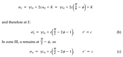
Therefore at A
in the orientation of the wall, the stresses on the wall from Mohr's
Circle are:
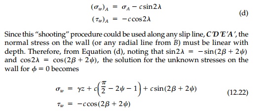
It is important to note
that the actual values of the wall stresses depend on the choice of Žł,
which specifies the extent of the circular zone II. The distribution of stress
on the wall however, is determined by the solution to be a constant shear and a
normal stress linear with depth. Any other distribution cannot be specified for
a unique solution to this Cauchy problem and maintain the unloaded boundary
conditions on the surface BC.*
The direction of the resultant
stress on the wall varies since the normal stress increases with depth
while the shear stress is constant. Therefore, to talk about a constant ŌĆ£angle
of wall frictionŌĆØ ╬┤ is a misnomer.
However, we can compute the components of the force resultants on the wall by
integrating the stresses, i.e.,
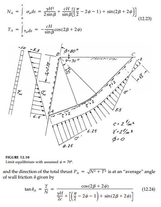
A specific example to
illustrate this complete stress solution at limit equilibrium for the case Žł=70┬ o is shown in Figure 12.10. For the passive case where the wall is forced
into the material, the failure surface is the same but the direction of
impending motion is revised. Thus the shear stress on the failure surface acts
in the opposite direction to resist the
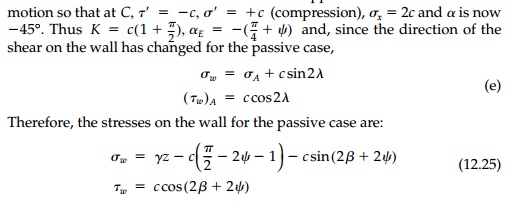
This is the same result
as for the active case except that the constants by which the geostatic normal
stress ╬│z is modified have changed sign,
as has the shear. The shear resultants N, T are modified
accordingly as is the average angle of wall friction.
Related Topics