Chapter: Civil : Principles of Solid Mechanics : Slip Line Analysis
Graphic Analysis and Minimization
Graphic Analysis and Minimization
In his paper, Coulomb
only derives the active pressure Equation (12.3b). However, although not stated
explicitly, this implies both the basic MohrCoulomb strength criterion,
Equation (3.16) and the passive pressure Equation (12.3a). The actual method
Coulomb used to obtain the minimum active and maximum passive forces was
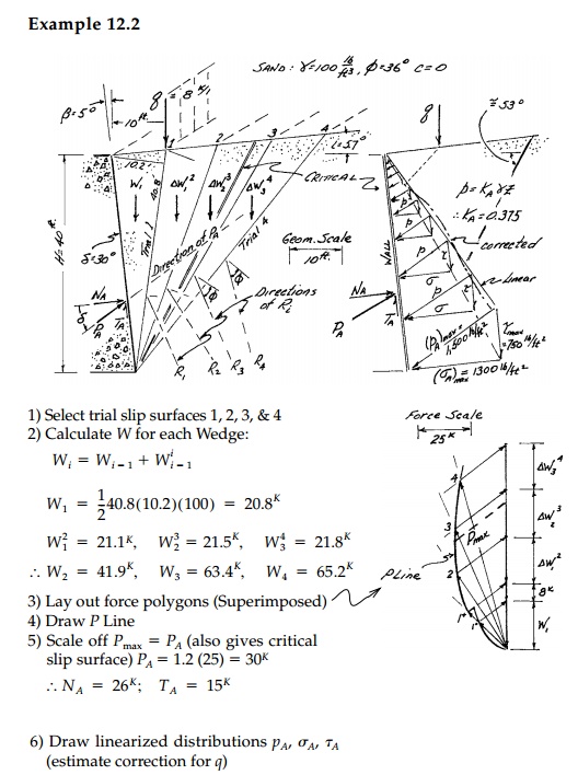
graphical. Developed in greater detail by Culmann*, Example 12.2 presents the
method for the active case. For any straight slipline trial,** a force diagram
can be drawn as in Figures 12.4c and d. By plotting a number of trials
superimposed, the maximum can be seen directly. This is similar in every
respect to the onedimensional problem of the collapse of an indeterminate beam
as in Figure 11.5 where a graphical minimization is used to determine the limit
load and position of the plastic hinges (critical collapse mechanism)
simultaneously. For retaining walls, however, the computation of the thrust for
each trial is also done graphically.
For homogeneous cases
with c = 0, straight boundaries, and no external loading, the forces can
be expressed in terms of the geometric variables β,
i, and friction angles δ, ϕ to obtain a closed form expression for P. This can be formally minimized
or maximized to obtain formulas for the active and passive thrusts and the
critical straightline slip surfaces associated with them. These will be given
in the concluding section of this session.
However, the graphical method for any particular
case is very quick and much more general. With the basic assumption of a
straight slip surface, any shaped wall, wall roughness, backfill geometry,
layered backfill with discontinuous c, Ď•, Îł,
condition of the water table, or practically any other complexity can be
included with very little additional work. Moreover, it is a design as much as
an analysis approach. Thus Coulomb’s method of analysis, relying on successive
applications of graphic statics, is as much of an accomplishment, in its way,
as are his equations.

Example 12.3
a.
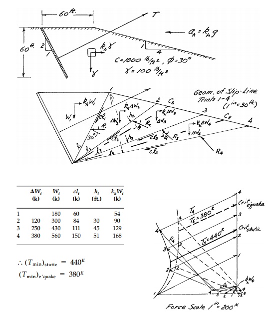
An anchor for a bridge tower is designed
as shown below. Assume no wall friction and neglecting any active pressures
behind the wall, determine the ultimate (limiting) static passive resistance TL
of the anchor.
b.Modify your analysis to include inertial forces
due to an earthquake with a peak horizontal acceleration ah =
0.3g. Show the difference between the seismic and static value for TL
and the critical seismic and static slip surfaces.

Related Topics