Chapter: Civil : Principles of Solid Mechanics : Slip Line Analysis
Mohr-Coulomb Criterion (Revisited)
Mohr-Coulomb Criterion (Revisited)
All materials have some component of frictional
strength and therefore are stronger in compression than tension. For EPS materials
(e.g., steel), this dif-ference is insignificant, but for cast iron, rock,
concrete, or soil, frictional strength predominates and cannot be neglected.
The Mohr-Coulomb crite-rion introduced in previews pages has the fundamental
form:
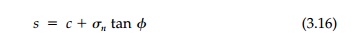
which plots as a straight line in stress space. Thus
the shear strength, s, is a linear function of the normal stress Žān
on the potential slip plane where tan ŽĢ is the coefficient of
friction.
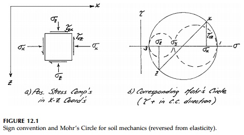
Since very ŌĆ£brittleŌĆØ materials such as concrete have little tensile strength and granular materials like sand have none, we will, in this session pages, reverse the arbitrary sign conventions of elasticity. Thus, compression will be positive and shear stresses will be positive if the signs of the subscripts are mixed. The con-vention for plotting MohrŌĆÖs Circle is shown in Figure 12.1. Also, throughout, it will be assumed that we have a plane-strain situation where the out-of-plane normal stress, Žāy , is intermediate. That is:
Therefore the slip
planes on which Žä' s are in the xŌĆ'z
plane and only the largest MohrŌĆÖs Circle need be plotted in future figures.
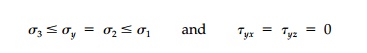
One fundamental
difference introduced by the M-C criterion is the possibility of two potential
failure states and two sets of slip surfaces, ŌĆ£activeŌĆØ and ŌĆ£passiveŌĆØ at a
point, even when one principal stress component is the same. This is easily
seen in the triaxial ŌĆ£testŌĆØ situation shown in Figure 12.2. Assuming this M-C
material is initially at constant hydrostatic pressure Žāxi + Žāzi
=
p, the specimen can be brought to failure (Mohr ŌĆÖs Circle touching the
strength envelope) by either increasing Žāx
(Figure 12.2a) or decreasing Žā x (Figure 12.2b) resulting in different sized and
oriented Mohr Circles as shown in Figure 12.2c.
It is useful to go through a formal plastic analysis
for either the active or passive case (although the result is obtained by
simply drawing MohrŌĆÖs Circle touching the strength envelope as in Figure
12.2c). Consider, for example, the passive case illustrated again in Figure
12.3 where the stress field is constant (b any size). Note that the active case
would give the same stressed element rotated 90┬ o where Žāx would now be the
minimum principal stress and Žā z the major. Thus, in terms of the orientation of the
principal stress components to the slip surfaces, there is no difference
between the active and passive case.
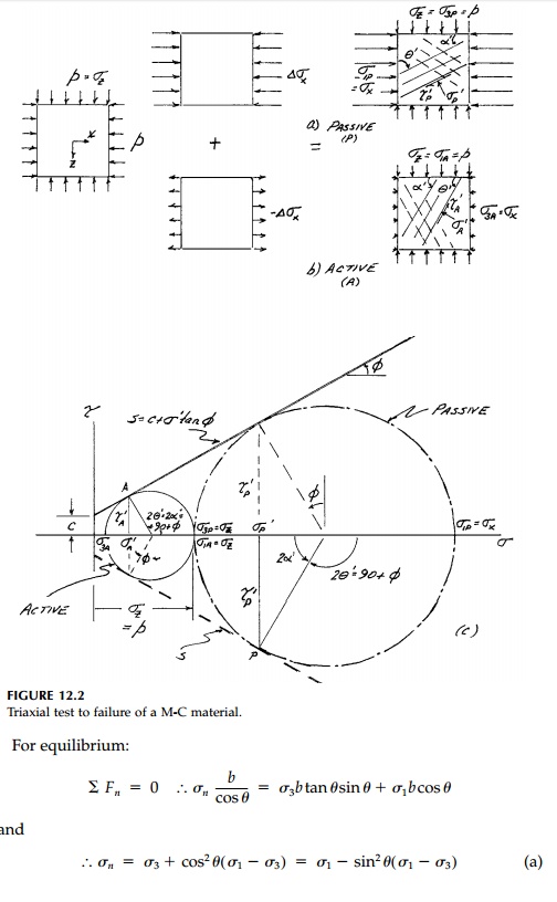
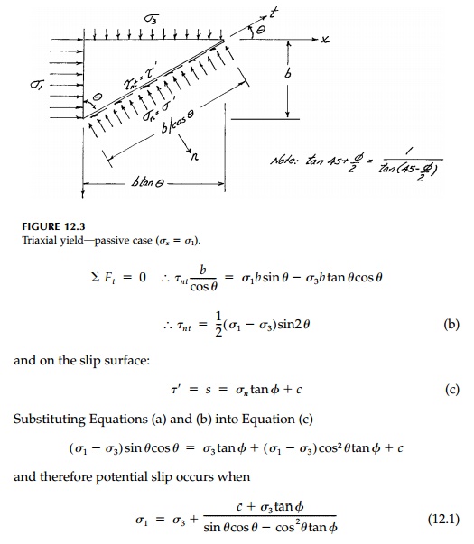
which apply in the principal stress orientation for either the active or passive case. Thus only when Žāx or Žāz is specified does the question arise of which ŌĆ£type of failureŌĆØ occurs.
Finally, it is important to reemphasize that the
block in Figure 12.3 can be thought of as a differential element (b = db)
and therefore the analysis and equations are general for a point. However, they
only apply on a finite scale in a stress field where the orientation of the
principal stresses (the isoclinic field) is constant. This is not the normal
situation. Thus a straight slip surface as an overall failure mechanism for
limit analysis, while it may be a nice guess, can seldom be exact.
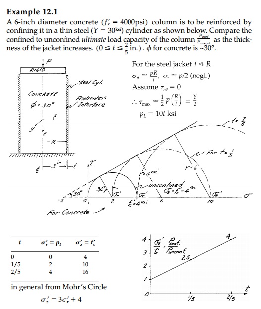
Demonstrating why, because of frictional strength,
encased concrete columns are so much stronger.
Related Topics