Chapter: Television and Video Engineering : Essentials of Color Television
Purity and Convergence
PURITY AND CONVERGENCE
While deflecting the three beams by vertical and horizontal deflecting coils it is necessary to ensure that each beam produces a pure color and all the three color rasters fully overlap each other.
For obtaining color purity each beam should land at the center of the corresponding phosphor dot irrespective of the location of the beams on the raster. This needs precise alignment of the color beam and is carried out by a circular magnet assembly known as the purity magnet.
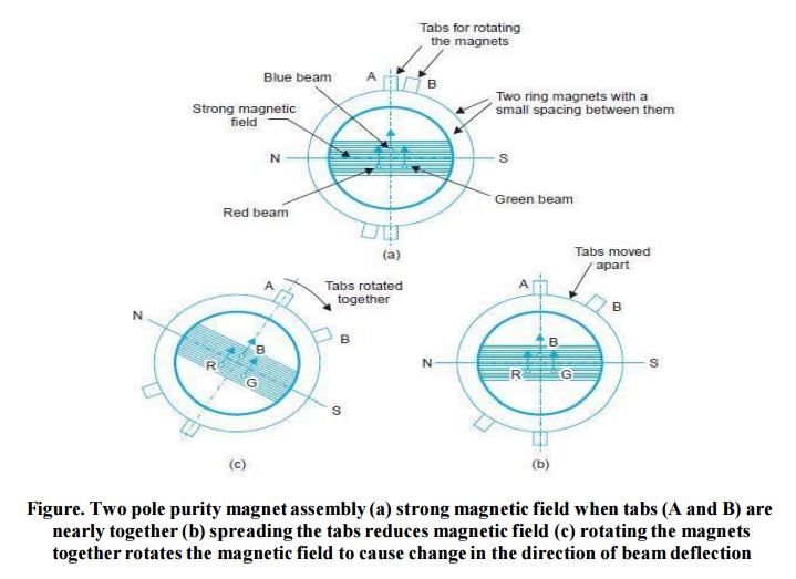
It is mounted externally on the neck of the tube and close to the deflection yoke. The purity magnet assembly consists of several flat washer like magnets held together by spring clamps in such a way that these can be rotated freely.
The tabs on the magnets can be moved apart to reduce resultant field strength. This is illustrated for a two pole magnet in Fig.
As shown in the same figure, the tabs when moved together change the direction of magnetic field. Two, four and six pole magnet units are employed to achieve individual and collective beam deflections. Thus to affect purity and static convergence the beams can be deflected up or down, right or left and diagonally by suitably orienting the purity magnets.
Yoke Position
The position of the yoke on the tube neck determines the location of the deflection centre of the electron beams. A wrong setting will result in poor purity due to improper entry angles of the beams into the mask openings.
Since deflection due to yoke fields affects the landing of the beams on the screen more towards the edges of the tube, the yoke is moved along the neck of the tube to improve purity in those regions.
Convergence
The technique of bringing the beams together so that they hit the same part of the screen at the same time to produce three coincident rasters is referred to as convergence. Convergence errors are caused by (i) non-coincident convergence planes, (ii) non uniformity of the deflection field and (iii) flat surface of the picture tube screen. Figure illustrates correct and incorrect convergence of beams.
Proper convergence is achieved by positional adjustment of the individual beams. It falls into two parts referred to as (i) static and (ii) dynamic convergence.
Static convergence involves movement of the beams by permanent magnetic fields which, once correctly set, bring the beams into convergence in the central area of the screen. Convergence over the rest of the screen is achieved by continuously varying (dynamic) magnetic fields, the instantaneous strengths of which depend upon the positions of the spots on the screen.
These fields are set up by electromagnets which carry currents at horizontal(line) and vertical (field) frequencies. In practice convergence coils are often connected in series with respective yoke windings.
Purity and Static Convergence
Modern P.I.L. tubes are manufactured with such precision that hardly any purity and static convergence adjustments are necessary. However, to correct for small errors due to mounting tolerances and stray magnetic fields multi pole permanent magnet units are provided.
Such a unit is mounted on the neck of the tube next to the deflection yoke. The various magnets are suitably oriented to achieve color purity, static convergence and straightness of horizontal raster lines.
Convergence Errors
The need for the three rasters to be accurately superposed on each other with no east to west (lateral) or north to south (vertical) displacement (i.e., in proper color register) puts stringent constraints on distribution of the deflection field.
Non-optimum distribution of the field along with the fact that the screen is a nearly flat surface (and not spherical) can produce two kinds of lack of color registration, commonly known as convergence errors.
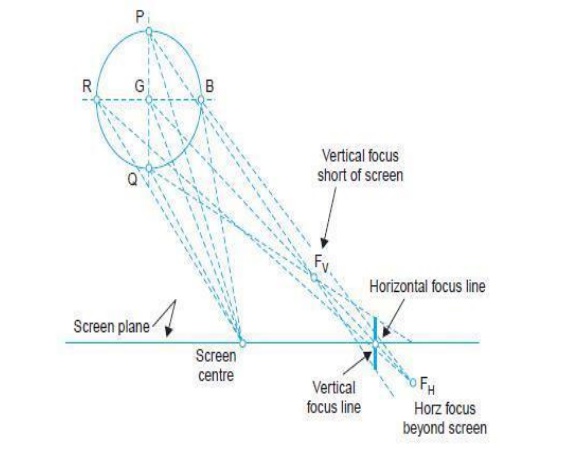
These are (a) astigmatism and (b) coma effects.(a) Astigmatism. As shown in Fig. (a), with a uniform field the rays from a vertical row of points (P, G, Q) converge short of the screen producing a vertical focal line on the screen. However, rays (R, G, B) from a row of horizontal points converge beyond the screen producing a horizontal line on the screen.
Such an effect is known as astigmatism and causes convergence errors. In the case of a P.I.L. tube, beams R, G and B emerge only from a horizontal line and so any vertical astigmatism will have no effect. However, if horizontal astigmatism is to be avoided, the horizontal focus must be a point on the screen and not a line for any deflection.
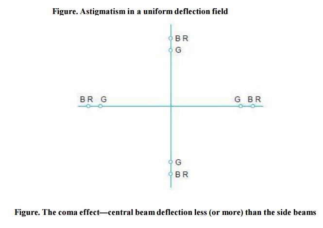
A given change in the shape of the deflection field produces opposite changes in vertical and horizontal astigmatic effects. Since vertical astigmatism is of no consequence in a P-I-L tube, suitable field adjustments can be made to ensure that the beams coming from in-line guns in a horizontal line converge at the same point on the screen irrespective of the deflection angle. Such a correction will however, be at the cost of a much larger vertical astigmatism but as stated above it does not interfere with the correct registration of various colors.(b) Coma Effect.
Due to non-uniformity of the deflection field all the beams are not deflected by the same amount. As shown in Fig (b) the central beam (green) deflects by a smaller amount as compared to the other two beams.
For a different non-uniformity of the deflection field, the effect could be just opposite producing too large a displacement of the central beam. Such a distortion is known as coma and results in mis-convergence of the beams.
Field Distribution for Optimum Convergence
In order to correct astigmatic and coma effects different field configurations are necessary. To help understand this, it is useful to visualize the deflection field in roughly two parts, the half of it closer to the screen and the other half closer to the guns.
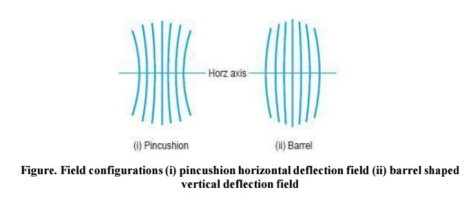
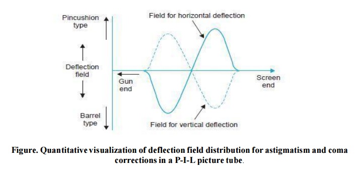
Astigmatism is caused by only that part of the field which is closer to the screen whereas coma effects occur due to non uniformities of the field all over the deflection area. To correct for mis convergence due to astigmatism in a P.I.L. tube the horizontal deflection field must be pincushion shaped and the vertical deflection field barrel shaped (Fig.) in the half near the screen.
But such a field configuration produces undue amounts of coma error. To circumvent this, the gun end of the field can be modified in such a way that the coma produced by the screen end field is just neutralized, thus giving a scan that is free from all convergence errors.
This needs that the field distribution at the gun end be barrel shaped horizontally and pincushion vertically. The above two requirements are illustrated in Fig. (b) which shows necessary details of horizontal and vertical field distributions relative to each other along the axis of the tube.
Though complicated, the above constraints of field distribution are met by proper deflection coil design and thus both astigmatic and coma effects are eliminated.
Related Topics