Chapter: Television and Video Engineering : Essentials of Color Television
Dynamic Convergence Adjustments
DYNAMIC CONVERGENCE ADJUSTMENTS
The
display unit consisting of picture tube and deflection unit is inherently
self-converging. However, small adjustments become necessary and are provided.
For this purpose two types of four-pole dynamic magnetic fields are used.
One is
generated by additional windings on the yoke ring of the deflection unit. It is
energized by adjustable sawtooth currents synchronized with scanning. The other
type of dynamic field is generated by sawtooth and parabolic currents which are
synchronized with scanning and flow through the deflection coils. (i) Line
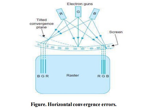
symmetry. Figure (a) shows a situation in which the plane where the beams are
converged automatically is slightly tilted with respect to the screen plane due
to some small left-right asymmetry in the distribution of the horizontal
deflection field.
As a result, horizontal convergence errors of
opposite signs occur at the sides of the screen. The same type of error can be
caused by a horizontal deviation of the un deflected beams from the screen
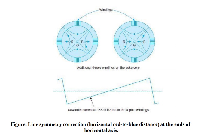
center. As shown in Fig. (b) such an error can be corrected by a 4-pole field
aligned diagonally with respect to the deflection fields. This field is
generated by driving a sawtooth current at line frequency through an additional
four-pole winding provided around the core of the deflection yoke.
The
sawtooth current is obtained directly from the line deflection circuit. (ii)
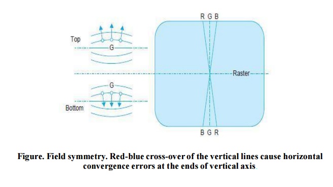
Field symmetry. As illustrated in Fig. vertical displacement of the plane of
the beams with respect to the center of the vertical deflection causes
horizontal convergence errors during vertical deflection.
These
errors can be corrected by feeding a rectified sawtooth current at field
frequency through the additional 4-pole winding on the deflection unit. (iii)
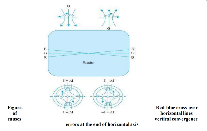
Line balance. Vertical displacement of the plane of beams with respect to
center of the horizontal deflection field causes cross-over of the horizontal
red and blue lines.
This
illustrated in Fig. The same type of error can also be caused by top-bottom
asymmetry of the horizontal deflection field. It can be corrected by a
four-pole field which is aligned orthogonally with respect to the deflection
fields.
Such a
field is generated by unbalancing (see corresponding figures) the line
deflection current through the two halves of the horizontal deflection coils
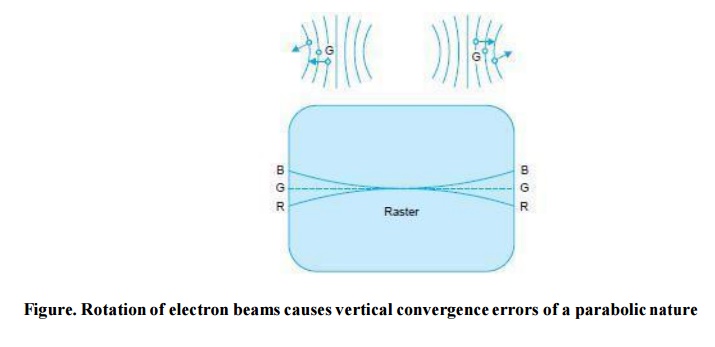
acted with respect to its normal orientation, a parabolic vertical convergence
error occurs during both horizontal and vertical deflection (Fig.).
This
error can be corrected by feeding a parabolic current at line frequency through
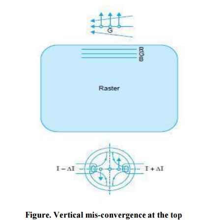
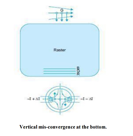
the line deflection coils.(v) Field balance at top and bottom. Left-right
asymmetry of the vertical deflection field or horizontal deviation of the
un-deflected beams from the screen center causes vertical convergence errors
during vertical deflection.
This is
illustrated (Fig) separately for top and bottom of the screen. The correction
at the top is made by unbalancing the field deflection coils during the
first-half of the field scan. Similarly correction at the bottom is made by
unbalancing the field deflection coils during the second-half of the field
scan.
Related Topics