Chapter: Television and Video Engineering : Essentials of Color Television
Modulation of Color Difference Signals
MODULATION OF COLOR DIFFERENCE
SIGNALS
The
problem of transmitting (B-Y) and (R-Y) video signals simultaneously with one
carrier frequency is solved by creating two carrier frequencies from the same
color subcarrier without any change in its numerical value.
Two
separate modulators are used, one for the (B-Y) and the other for the (R-Y)
signal. However, the carrier frequency fed to one madulator is given a relative
phase shift of 90° with respect to the other before applying it to the
modulator.
Thus, the
two equal subcarrier frequencies which are obtained from a common generator are
said to be in quadrature and the method of modulation is known as quadrature
modulation.
After
modulation the two outputs are combined to yield C, the resultant subcarrier
phasor. Since the amplitude of C, the chrominance signal, corresponds to the
magnitudes of color difference signals, its instantaneous value represents
color saturation at that instant.
Maximum
amplitude corresponds to greatest saturation and zero amplitude to no
saturation i.e., white. Similarly, the instantaneous value of the C phasor
angle (θ) which may vary from 0° to 360° represents hue of the color at that
moment.
Thus the
chrominance signal contains full information about saturation and hue of
various colors. This being a crucial point in color signal transmission, is
illustrated by a few examples. However, it would be necessary to first express
(R-Y) and (B-Y) in terms of the three camera output voltages.
This is
done by substituting Y = 0.59G + 0.3R + 0.11B in these expressions.
Thus
(R-Y) becomes R – 0.59G – 0.3R – 0.11B = 0.7R – 0.59G – 0.11B.
Similarly,
(B-Y) becomes B – 0.59G – 0.3R – 0.11B = 0.89B – 0.59G – 0.3R.
Now
suppose that only pure red color is being scanned by the color camera. This
would result in an output from the red camera only, while the green and blue
outputs will be zero. Therefore, (R-Y) signal will become simply + 0.7R and
(B-Y) signal will be reduced to – 0.3R.
The
resultant location of the subcarrier phasor after modulation is illustrated in
Fig. Note that the resultant phasor is counter clockwise to the position of +
(R-Y) phasor. Next consider that the color camera scans a pure blue color
scene.
This
yields (R-Y)= – 0.11B and (B-Y) = 0.89 B. The resultant phasor for this color
lags + (B-Y) vector by a small angle. Similarly the location and magnitude for
any color can be found out. This is illustrated in Fig. for the primary and
complementary colors.
Another
point that needs attention is the effect of desaturation on the color phasors.
Since desaturation results in reduction of the amplitudes of both (B-Y) and
(R-Y) phasors, the resultant chrominance phasor accordingly changes its
magnitude depending on the degree of de-saturation.
Thus any change in the purity of a color is
indicated by a change in the magnitude of the resultant subcarrier phasor.
Color Burst Signal Suppressed carrier double sideband working is the normal
practice for modulating color- difference signals with the color subcarrier
frequency.
This is
achieved by employing balanced modulators. The carrier is suppressed to
minimize interference produced by the chrominance signals both on monochrome
receivers when they are receiving color transmissions and in the luminance
channel of color receivers themselves. As explained in an earlier chapter the
ratio of the sideband power to carrier power increases with the depth of
modulation.
However,
even at 100% modulation two-thirds of the total power is in the carrier and
only one-third is the useful sideband power. Thus suppressing the carrier
clearly eliminates the main potential source of interference.
In
addition of this, the color-difference signals which constitute the modulating
information are zero when the picture detail is non-colored (i.e., grey, black
or white shades) and so at such times the sidebands also disappear leaving no
chrominance component in the video signal.
As
explained above the transmitted does not contain the subcarrier frequency but
it is necessary to generate it in the receiver with correct frequency and phase
relationship for proper detection of the color sidebands.
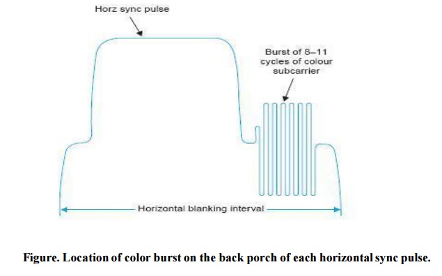
To ensure
this, a short sample of the subcarrier oscillator, 8 to 11 cycles) called the
‘color burst’ is sent to the receiver along with sync signals. This is located
in the back porch of the horizontal blanking pedestal.
The color
burst does not interfere with the horizontal sync because it is lower in
amplitude and follows the sync pulses. Its exact location is shown in Fig.
The color
burst is gated out at the receiver and is used in conjunction with a phase
comparator circuit to lock the local subcarrier oscillator frequency and phase
with that at the transmitter.
As the
burst signal must maintain a constant phase relationship with the scanning
signals to ensure proper frequency interleaving, the horizontal and vertical
sync pulses are also derived from the subcarrier through frequency divider
circuits.
Related Topics