Chapter: Television and Video Engineering : Essentials of Color Television
Delta-Gun Color Picture Tube
DELTA-GUN COLOR PICTURE TUBE

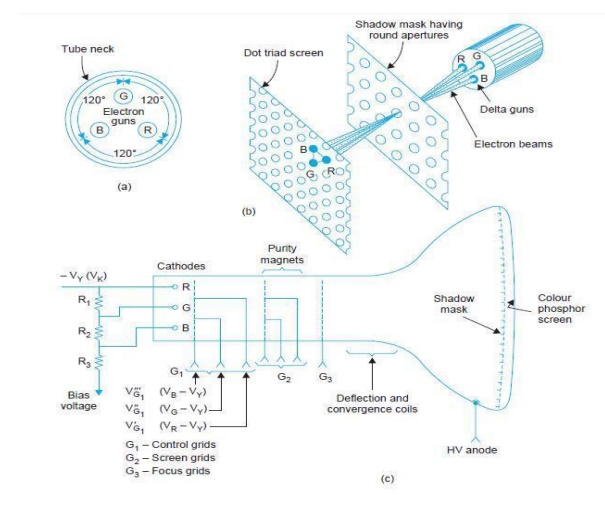
This tube
was first developed by the Radio Corporation of America (R.C.A.). It employs
three separate guns (see Fig. (a)), one for each phosphor. The guns are equally
spaced at 120° interval with respect to each other and tilted inwards in
relation to the axis of the tube.
They form
an equilateral triangular configuration. As shown in Fig. (b) The tube employs
a screen where three color phosphor dots are arranged in groups known as
triads. Each phosphor dot corresponds to one of the three primary colors.
The
triads are repeated and depending on the size of the picture tube,
approximately 1,000,000 such dots forming nearly 333,000 triads are deposited
on the glass face plate.
About one
cm behind the tube screen (see Figs. (b) And (c)) is located a thin perforated
metal sheet known as the shadow mask. The mask has one hole for every phosphor
dot triad on the screen. The various holes are so oriented that electrons of
the three beams on passing through any one hole will hit only the corresponding
color phosphor dots on the screen.
The ratio of electrons passing through the
holes to those reaching the shadow mask is only about 20 percent. The remaining
80 percent of the total beam current energy is dissipated as a heat loss in the
shadow mask.
While the
electron transparency in other types of color picture tubes is more, still,
relatively large beam currents have to be maintained in all color tubes
compared to monochrome tubes. This explains why higher anode voltages are
needed in color picture tubes than are necessary in monochrome tubes.
Generation
of Color Rasters The overall color seen is determined both by the intensity of
each beam and the phosphors which are being bombarded. If only one beam is ‘on’
and the remaining two are cut-off, dots of only one color phosphor get excited.
Thus the raster will be seen to have only one of the primary colors. Similarly,
if one beam is cut-off and the remaining two are kept on, the rasters produced
by excitation of the phosphors of two colors will combine to create the
impression of a complementary color.
The exact
hue will be determined by the relative strengths of the two beams. When all the
three guns are active simultaneously, lighter shades are produced on the
screen. The is so because red, green and blue combine in some measure to form
white, and this combines with whatever colors are present to de-saturate them.
Naturally,
intensity of the color produced depends on the intensity of beam currents.
Black in a picture is just the absence of excitation when all the three beams
are cut-off. If the amplitude of color difference signals drops to zero, the
only signal left to control the
three
guns would be the Y signal and thus a black and white (monochrome) picture will
be produced on the screen. Primary Color Signals.
The
demodulators in the receiver recover (B – Y) and (R – Y) video signals. The (G
– Y) color video signal is obtained from these two through a suitable matrix.
All the three color difference signals are then fed to the three grids of color
picture tube (see Fig (c)).
The
inverted luminance signal (– Y) is applied at the junction of the three
cathodes. The
signal
voltages subtract from each other to develop control voltages for the three
guns,
i.e., V′ G1 – V k = (V R – V Y ) – (– V Y ) = V R
V′′ G1 –
V k = (V G – V Y ) – (– V Y ) = V G and
In some
receiver designs the Y signal is subtracted in the matrix and resulting color
voltages are directly applied to the corresponding control grids. The cathode
is then returned to a fixed negative voltage.
Related Topics