Chapter: Television and Video Engineering : Essentials of Color Television
Color Television Camera
COLOR TELEVISION CAMERA
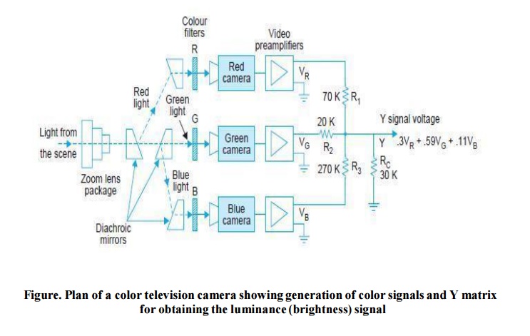
Figure shows a simple block schematic of a color TV camera. It essentially consists of three camera tubes in which each tube receives selectively filtered primary colors.
Each camera tube develops a signal voltage proportional to the respective color intensity received by it. Light from the scene is processed by the objective lens system. The image formed by the lens is split into three images by means of glass prisms.
These prisms are designed as diachroic mirrors. A diachroic mirror passes one wavelength and rejects other wavelengths (colors of light).Thus red, green, and blue color images are formed. The rays from each of the light splitters also pass through color filters called trimming filters.
These filters provide highly precise primary color images which are converted into video signals by image-orthicon or vidicon camera tubes. Thus the three color signals are generated. These are called Red (R), Green (G) and Blue (B) signals. Simultaneous scanning of the three camera tubes is accomplished by a master deflection oscillator and sync generator which drives all the three tubes.
The three video signals produced by the camera represent three primaries of the color diagram. By selective use of these signals, all colors in the visible spectrum can be reproduced on the screen of a special (color) picture tube.
Color Signal Generation
At any instant during the scanning process the transmitted signal must indicate the proportions, of red, green and blue lights which are present in the element being scanned. Besides this, to fulfil the requirements of compatibility, the luminance signal which represents the brightness of the elements being scanned must also be generated and transmitted along with the color signals.
Figure illustrates the method of generating these signals. The camera output voltages are labelled as V R, V G and V B but generally the prefix V is omitted and only the symbols R, G, and B are used to represent these voltages. With the specified source of white light the three cameras are adjusted to give equal output voltage.
Gamma Correction
To compensate for the non-linearity of the system including TV camera and picture tubes, a correction is applied to the voltages produced by the three camera tubes.
The output voltages are then referred as R′, G′ and B′. However, in our discussion we will ignore such a distinction and use the same symbols i.e., R, G and B to represent gamma corrected output voltages.
Furthermore, for convenience of explanation the camera outputs corresponding to maximum intensity (100%) of standard white light to be handled are assumed adjusted at an arbitrary value of one volt. Then on grey shades, i.e., on white of lesser brightness, R, G and B voltages will remain equal but at amplitude less than one volt.
Related Topics