Chapter: Electrical and electronics : Circuit Theory
Nodal Analysis
NODAL ANALYSIS:
Nodal analysis involves looking at a circuit and determining all the node voltages in the circuit. The voltage at any given node of a circuit is the voltage drop between that node and a reference node (usually ground). Once the node voltages are known any of the currents flowing in the circuit can be determined. The node method offers an organized way of achieving this.
Approach:
Firstly all the nodes in the circuited are counted and identified. Secondly nodes at which the voltage is already known are listed. A set of equations based on the node voltages are formed and these equations are solved for unknown quantities. The set of equations are formed using KCL at each node. The set of simultaneous equations that is produced is then solved. Branch currents can then be found once the node voltages are known. This can be reduced to a series of steps:
Step 1: Identify the nodes
Step 2: Choose a reference node
Step 3: Identify which node voltages are known if any Step 4: Identify the BRANCH currents
Step 5: Use KCL to write an equation for each unknown node voltage Step 6: Solve the equations
This is best illustrated with an example. Find all currents and voltages in the following circuit using the node method. (In this particular case it can be solved in other ways as well)
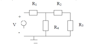
Step 1:
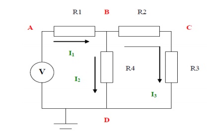
There are four nodes in the circuit. A, B, C and D
Step 2:
Ground, node D is the reference node.
Step 3:
Node voltage B and C are unknown. Voltage at A is V and at D is 0
Step 4:
The currents are as shown. There are 3 different currents
Step 5:
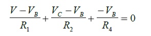
I need to create two equations so I apply KCL at node B and node C
The statement of KCL for node B is as follows:
The statement of KCL for node C is as follows:
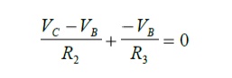
Step 6:
We now have two equations to solve for the two unknowns VB and VC. Solving the above two equations we get:
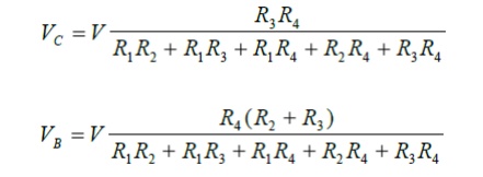
Further Calculations
The node voltages are know all known. From these we can get the branch currents by a simple application of Ohm's Law:
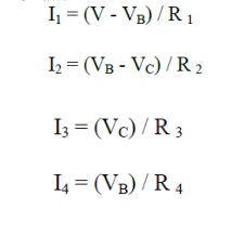
Problem 1: Find the current through each resistor of the circuit shown in fig, using nodal analysis
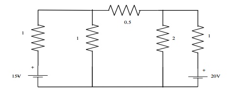
Solution:
At node1,
-I1-I2-I3 = 0 -[V1-15/1]-[V1/1][V1-V2/0.5] = 0
-V1+15-V1-2V1+2V2 = 0
4V1-2V2 = 15 --------------------- (1)
At node2,
I3-I4-I5 = 0
V1-V2/0.5 ŌĆōV2/2 ŌĆōV2-20/1 = 0
2V1-2V2-0.5V2-V2 + 20 = 0
2V1-3.5V2 = -20 ------------------ (2)
Multiplying (2) by 2 & subtracting from (1)
5V2 = 55 V2 = 11V V = 9.25V
I1 = V1-5/1 = 9.25-15 = -5.75A = 5.75 I2 = V1/1 = 9.25A
I3 = V1-V2/0.5 = -3.5A = 3.5A ├¤ I4 = V2/2 = 5.5A
I5 = V2-20/I = 11-20/1 = -9A=9A.
Problem 2: For the bridge network shown in Figure determine the currents in each of the resistors.
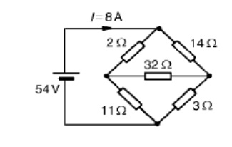
Let the current in the 2 resistor be I1, and thens currentby law,KirchhoffŌĆÖthecurrentinthe14 resistor is (I -I1). Let the current in the 32 resistor be I2 as shown in Figure Then the current in the 11 resistor is (I1 - I2) and that in the 3 resistor is (I - I1 + I2). Applying KirchhoffŌĆÖs and moving in a clockwise direction as shown in Figure gives:
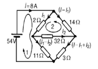
54 = 2I1 +11(I1 _-I2)
i.e. 13I1 - 11I2 = 54
Applying KirchhoffŌĆÖs voltage law to loop 2 and direction as shown in Figure gives:
0 = 2I1 + 32I2 -14(I - I1)
However I = 8 A
Hence 0 = 2I1 + 32I2 ŌĆō14(8 -_I1) i.e. 16I1 + 32I2 = 112
Equations (1) and (2) are simultaneous equations with two unknowns, I1 and I2.
16 * (1) gives: 208I1 _-176I2 = 864
16 * (1) gives: 208I1 _-176I2 = 864
13 * (2) gives: 208I1 + 416I2 = 1456
(4) - (3) gives: 592I2 = 592, I2 = 1 A
Substituting for I2 in (1) gives:
13I1 - 11 = 54
I1 = 65/13 = 5 A
Hence,
the current flowing in the 2 resistor = I1 = 5 A
the current flowing in the 14 resistor = I -I1 = 8 -5 = 3 A
the current flowing in the 32 resistor = I2 = 1 A
the current flowing in the 11 resistor = I1 - I2 = 5 -1 = 4 A and
the current flowing in the 3 resistor = I - I1 + I2 = 8 - 5 + 1 = 4 A
Problem 3: Determine the values of currents I, I1 and I2 shown in the network of Figure
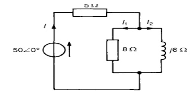
Total circuit impedance,
ZT = 5 + (8)(j6)/8 + j6
= 5 + (j48)(8 - j6)/82 + 62
= 5 + (j384 + 288)/100
= (7.88 + j3.84) or 8.776 25.98┬░ A Current I = V/ZT
= 50Ōł¤ 0┬░/8.77Ōł¤ 25.98┬░
= 5.7066 ŌłÆ25.98┬░ A
Current I1 = I (j6/8 + j6)
= (5.702Ōł¤5.98┬░) (6Ōł¤ 90┬░)/10Ōł¤ 36.87┬░
= 3.426Ōł¤27.15┬░ A
Current I2 = I (8/ (8 + j6)
= (5-.2570Ōł¤.98┬░)*8Ōł¤ 0┬░/10Ōł¤ 36.87┬░
= 4.5666 ŌłÆ62.85┬░ A
[Note: I = I1 + I2-62.=85┬░ 3.42 Ōł¤27.15┬░ + 4.56Ōł¤
= 3.043 + j1.561 + 2.081 - j4.058
= 5.124 - j2.497 A = 5.706 -25.98┬░ A
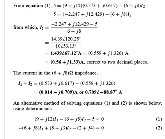
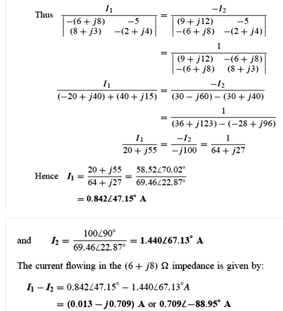
Problem 4: For the a.c. network shown in Figure, determine the current flowing in each branch using KirchhoffŌĆÖs laws.

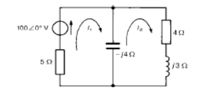
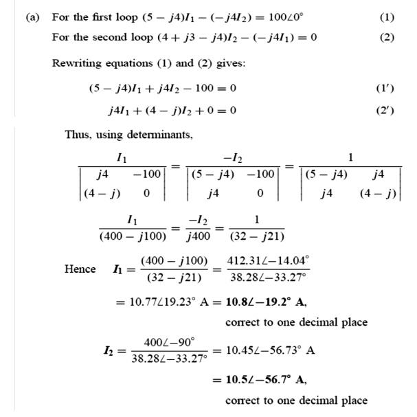
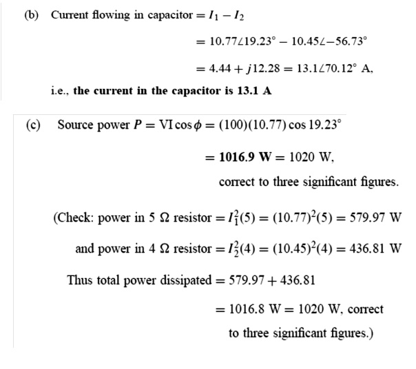
Problem 5: For the a.c. network shown in Figure determine, using mesh-current analysis, (a) the mesh currents I1 and I2 (b) the current flowing in the capacitor, and (c) the active power delivered by the 1006 0┬░ V voltage source.
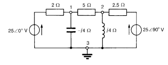
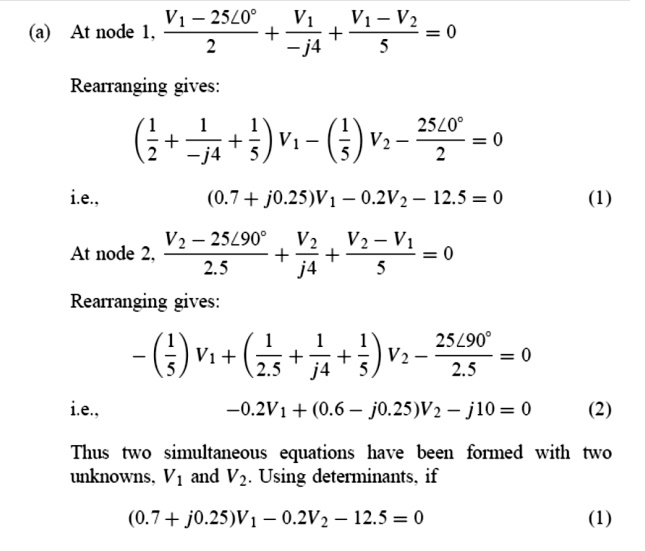
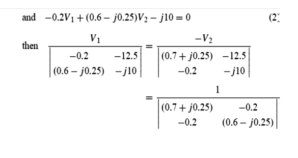
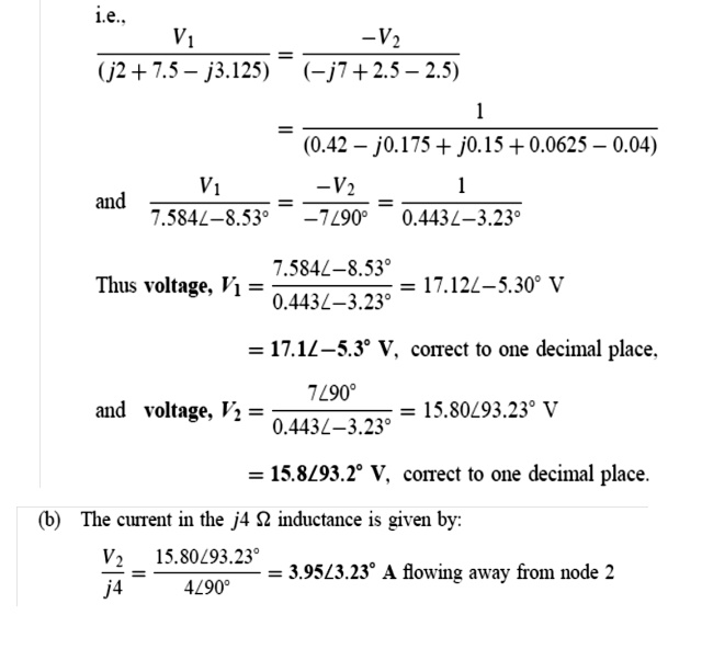
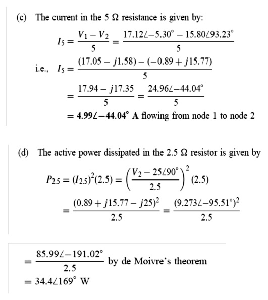
Problem 6: In the network of Figure use nodal analysis to determine (a) the voltage at nodes 1 and 2, (b) the current in the j4 ╬® inductance, (c) of the active power dissipated-10) in the 2.5 ╬®
Related Topics