Chapter: Electrical and electronics : Circuit Theory : Network Reduction and Network Theorems for DC And AC Circuits
Potential Divider
POTENTIAL DIVIDER:
The voltage distribution for the circuit shown in Figure
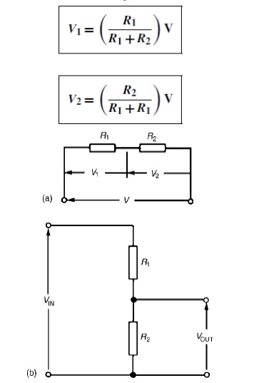
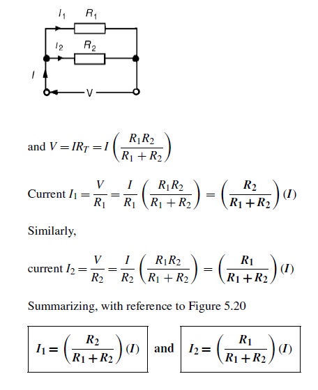
The circuit shown in Figure (b) is often referred to as a potential divider circuit. Such a circuit can consist of a number of similar elements in series connected across a voltage source, voltages being taken from connections between the elements. Frequently the divider consists of two resistors as shown in Figure (b), where
A potential divider is the simplest way of producing a source of lower e.m.f. from a source of higher e.m.f., and is the basic operating mechanism of the potentiometer, a measuring device for accurately measuring potential differences
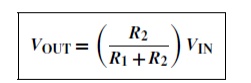
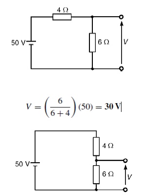
Problem 1: Determine the value of voltage V shown in Figure
Problem 2: Two resistors are connected in series across a 24V supply and a current of 3A flows in the circuit. If one of the resistors has resis and (b) the p.d. across the 2 ╬®resistor. If the circuit is connected for 50 hours, how much energy is used?
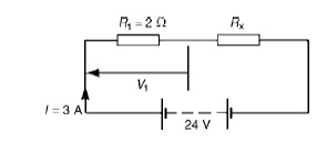
(a) Total circuit resistance R= V/ I
= 24/3=8 ╬® Value of unknown resistance, Rx =8 ŌłÆ2=6 ╬®
(b) P.d. across 2 ╬®resistor, V1 =IR1 =3 ├Ś 2=6V Alternatively, from above,
V1 = (R1/R1 + Rx)) V = (2/2 + 6) (24) = 6V Energy used = power ├Ś time
= V ├Ś I ├Ś t
= (24 ├Ś 3W) (50 h)
= 3600Wh = 3.6kWh
Current division:
For the circuit shown in Figure, the total circuit resistance, RT is given by:
RT = R1R2/R1 + R2
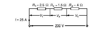
Problem 1: For the series-parallel arrangement shown in Figure, find (a) the supply current, (b) the current flowing through each resistor and (c) the p.d. across each resistor.
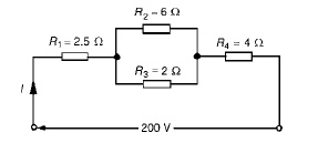
(a) The equivalent resistance Rx of R2 and R3 in parallel is: Rx = 6 ├Ś 2/6 + 2
= 12/8
= 1.5 ╬®
The equivalent resistance RT of R1, Rx and R4 in series is:
RT = 2.5 + 1.5 + 4 = 8 ╬® Supply current I = V/RT
= 200/8
= 25A
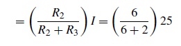
The current flowing through R1 and R4 is 25A The current flowing through R2
= 6.25A
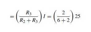
The current flowing through R3
= 18.75A
(c) The equivalent circuit of Figure is
p.d. across R1, i.e. V1 =IR1 =(25)(2.5)=62.5V p.d. across Rx, i.e. Vx =IRx =(25)(1.5)=37.5V p.d. across R4, i.e. V4 =IR4 =(25)(4)=100V
Hence the p.d. across R2 =p.d. across R3 =37.5V
Problem 2: For the circuit shown in Figure 5.23 calculate (a) the value of resistor Rx such that the total power dissipated in the circuit is 2.5kW, and (b) the current flowing in each of the four resistors.
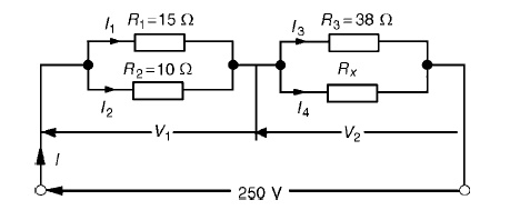
(a) Power dissipated P=VI watts, hence 2500=(250)(I) i.e. I = 2500/250
= 10A
From OhmŌĆÖsRT=V/I=law,250/10
=25 ╬®, where RT is the equivalent circuit resistance. The equivalent resistance of R1 and R2 in parallel is =15 ├Ś 10/15 + 10
= 150/25
= 6 ╬®
The equivalent resistance of resistors R3 and Rx in parallel is equal to 25 ╬®ŌłÆ6 ╬®, i.e. 19 ╬®. There are three methods whereby Rx can be determined.
Problem 3: For the arrangement shown in Figure find the current Ix.
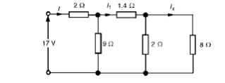
Commencing at the right-hand side of the arrangement shown in Figure, the circuit is gradually reduced in stages as shown in Figure
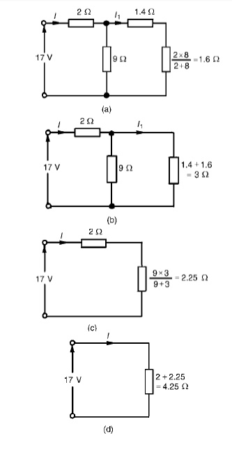
From Figure (d), I = 17/4.25 =4A
From Figure (b), I1 =9/9 + 3(I) = 12/ (4) =3A From Figure, Ix =2/2 + 8(I1) = 2/10(3) =0.6A
Source transformation:
Source transformation is defined as to concert the sources for easy analysis of circuit. In mesh analysis. it is easier if the circuit has voltage sources.
In nodal analysis. it is easier if the circuit has current sources.
Related Topics