Chapter: Electrical and electronics : Circuit Theory : Network Reduction and Network Theorems for DC And AC Circuits
NortonŌĆÖs Theorem
NORTONŌĆÖS THEOREM:
NortonŌĆÖs theorem states the following:
Any two-terminal linear bilateral dc network can be replaced by an equivalent circuit consisting of a current and a parallel resistor.
The steps leading to the proper values of IN and RN. Preliminary steps:
1. Remove that portion of the network across which the Norton equivalent circuit is found.
2. Mark the terminals of the remaining two-terminal network.
3. Finding RN:
Calculate RN by first setting all sources to zero and then finding the resultant resistance between the two marked terminals. Since RN = RTh the procedure and value obtained using the approach described for TheveninŌĆÖs theorem will determine the proper value of RN.
4. Finding IN :
Calculate IN by first returning all the sources to their original position and then finding the short-circuit current between the marked terminals. It is the same current that would be measured by an ammeter placed between the marked terminals.
5. Draw the Norton equivalent circuit with the portion of the circuit previously removed replaced between the terminals of the equivalent circuit.
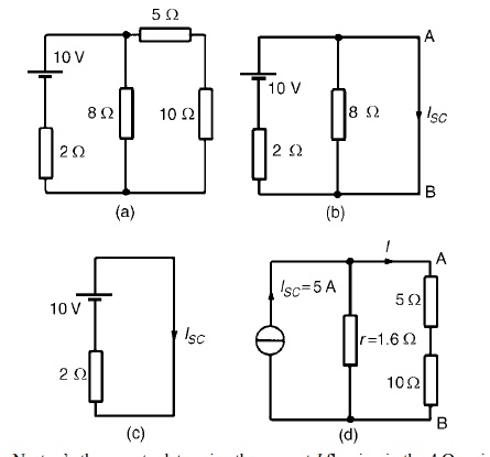
Problem 1: Use NortonŌĆÖs theorem to determine ╬® resistance for the the cur circuit shown in Figure
The branch containing the 10 ╬® resistance is short circuited as shown in Figure
Figure (c) is equivalent to Figure (b).Hence ISC = 10/2
= 5A
If the 10V source of e.m.f. is removed from Figure (b) the resistance ŌĆślooking-inŌĆÖ at a break made between A and B is given by:
r = 2 ├Ś 8/2 + 8 = 1.6 ╬®
From the Norton equivalent network shown in Figure(d) the current in the 10 ╬®resistance, by current division, is given by:
I = (1.6/1.6 + 5 + 10) (5) = 0.482A
as obtained previously in problem 7 using Th├®veninŌĆÖs theorem.
Problem 2: Problem 2: Use NortonŌĆÖs theorem to determine the current I flowing in the 4 ╬® resistance shown in Figure (a).
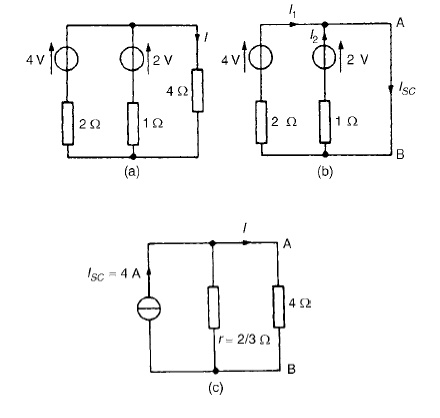
The 4 ╬®branch is short-circuited as shown in Figure (b). From Figure (b), ISC =I1 +I2 =4A
If the sources of e.m.f. are removed the resistance ŌĆślooking-inŌĆÖat a break made be given by:
r = 2 ├Ś 1/2 + 1 = 2/3 ╬®
From the Norton equivalent network shown in Figure (c) the current in the 4 ╬®resistance is given by:
I =(2/3/(2/3) + 4)(4) = 0.571A,
as obtained previously in problems 2, 5 and 9 us superposition and Th├®venin.
Related Topics