Chapter: Electrical and electronics : Circuit Theory : Transient Response For DC Circuits
Current lags and leads voltage in R-L series circuit
i) Current
lags voltage in R-L series circuit
ii) Current
leads voltage in R-C series circuit
Solution:
Current lags voltage in R-L series circuit
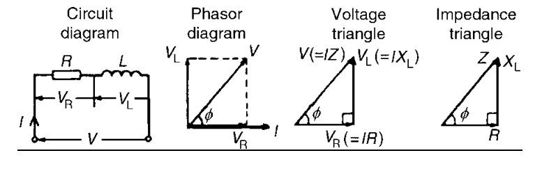
Consider a circuit consisting of pure Resistance R ohms connected
in series with Inductance L henries as shown in fig.
The series combination is
connected across ac supply is given by V = Vm Sinwt
The voltage drops in the circuit are,
Drop across pure resistance VR = IR
Drop across pure inductance
VL = IXL Where XL = 2πfL
I = rms value of current
drawn VR, VL = rms value of pure inductance
By
applying KVL,
V = IR + IX L
Steps to drawn phasor diagram:
1. I as reference phasor
2. R, V, I are in phase, So VR will be along I phase in
case of resistance
3. I lags voltage by 900. But I is
reference, VL must be shown leading w.r.t I by 900 in
case of inductance
4. Supply voltage = Vector sum of 2 vectors VL and VR
obtained by law of parallelogram
V = √ (VR2) + (VL2)
= √ ((IR) 2 + (IXL) 2)
= I √ (R2 + XL2)
V = IZ
Z = √ (R2
+ XL2)
From
voltage triangle we can write,
Tan ф = V L ∕VR
= X L ∕R Cos ф= VR∕V = R∕Z
Sin ф = V L ∕V =X L ∕Z
If all the sides of voltage are divided by current, we get triangle
called impedance triangle.
Side or triangles are,
1- Resistance R
2- Inductive reactance X L
3- Impedance Z
From this impedance triangle
R = Z Cos ф X
component of Impedance = R
X L = Z sin ф Y Component of Impedance = X L
In
rectangular form the impedance is denoted as,
Z = R + j X L
While in
polar form
Z = ∣Z∣∠ф Ω
Where,
∣Z∣ = √ (R2 + XL2)
ф = tan -1[XL∕R]
Impedance:
Impedance is defined as opposition of circuit to flow alternating
current. It is denoted by Z and the unit is ohms.
Power and power triangle:
The expression for the
current in the series R-L circuit is, i = Im Sin (wt-ф) as current lags voltage
Power =
V x i
= Vm Sin (wt) x Im Sin (wt-ф)
= VmIm[Sin(wt).Sin(wt-ф)]
= VmIm [ (Cosф – Cos (2wt-ф))∕2]
= (VmIm ∕2) x Cos ф - (VmIm ∕2) x Cos (2wt-ф)
Second
term is cosine term whose average value over a cycle is zero.
Average
power Pavg = (VmIm∕2) x Cos ф
= (Vm∕√2) x (Im∕√2) x Cos ф
P = VI Cos ф watt
The
three side of triangle is,
10.VI
11.VI Cos ф
12.VI Sin ф
These
three terms can be defined as below,
1. Apparent power(S):
It is defined as the product of rms value of
boltage (V) and current (I). it is denoted as ‘S’.
S = VI unit is VA VA – Voltage ampere
2. Real or true power (P):
It is defined as the product of applied voltage and active
component of the circuit. It is real component of the apparent power. It is
measured in watts (W) or kilowatts (KW)
P = VI Cos ф
watts
3. Reactive power (Q):
It is defined as product of applied voltage and reactive component
of current. It is also defined as the imaginary of apparent power is
represented by Q. Unit is VAR
Q = VI Sin ф VAR
Where
VAR – Volt ampere reactive.
I lead V in R-C
series circuit:
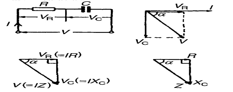
Consider a circuit in which resistance R ohms and capacitance C
farads is connected across ac supply is given by,
V = Vm Sin wt
Circuit
draws a current I, then there are two voltage drops,
5. Drop across pure resistance VR = IR
6. Drop across pure capacitance Vc = IXc
Where,
Xc = 1∕2πfC
Apply
KVL we get,
V=VR
+ VC
V = IxR
+IxXC
Steps to draw phasor diagram:
Ø Take current as reference phasor.
Ø In case of resistance, voltage and current are
in phase, so, VR will along current phasor.
Ø In case of capacitance, current leads voltage
900 i.e. voltage lags by 900. so, Vc is shown downwards
(i.e.) lagging current by 900
Ø The supply voltage being vector sum of these
two voltages Vc and VR obtained by completing parallelogram
Form
voltage triangle,
V = √ ((VR2) + (Vc2))
= √(( IR2) + (IXc2))
= I √ (R2 + Xc2)
V = IZ
Z = √(R2 + Xc2) is the
impedance of circuit
Impedance:
Impedance is nothing but opposition of flow of alternating current.
It is measured in ohms given by,
Z = √(R2 + Xc2)
Where, Xc = 1∕1∕2πfC Ω called
capacitive reactance.
From voltage triangle if all sides of voltage triangle are divided
by current, we get impedance triangle.
The
sides of triangle are R, Xc, Z
The X
component is R = Z Cos ф The Y component is Xc = Z Sin ф
But
direction of Xc is –Ve direction
Z = R- j Xc Ω - Rectangular form Z = ∣Z∣∠-ф Ω - Polar form
Where,
∣Z∣ = √ (R2 + Xc2)
ф = tan -1[-Xc∕R]
Power and power triangle:
The I leads the V by angle ф
hence, i = Im Sin (wt + ф)
Power = V x i
= Vm Sin (wt) x Im Sin (wt + ф)
= VmIm[Sin(wt).Sin(wt + ф)]
= VmIm [ (Cos(-ф) – Cos (2wt + ф))∕2]
= (VmIm ∕2) x Cos ф - (VmIm ∕2) x Cos (2wt + ф)
Second
term is cosine term whose average value over a cycle is zero.
Average
power Pavg = (VmIm∕2) x Cos ф
= (Vm∕√2) x (Im∕√2) x Cos ф P = VI Cos ф watts
If we
multiply voltage equqtion by current I we get power equation,
1. Apparent power (S)
2. Real or true power (P)
3. Reactive power (Q)
Note:
Z = R + j XL = Z = ∣Z∣∠ф Ω ; ф is +Ve for Inductive Z
P = VI Cos ф ;Cos ф is
lagging for Inductive circuit
Z = R - j XL = Z = ∣Z∣∠-ф Ω ; ф is -Ve for Capacitive Z
P = VI Cos ф ;Cos ф is
leading for Capacitive circuit
Related Topics