Chapter: Electrical and electronics : Circuit Theory : Transient Response For DC Circuits
Time constant and step response of series RL circuit
1) What is time constant? Explain time constant in case of series RL circuit.
Or
3) Explain in brief about the step response of
series RL circuits.
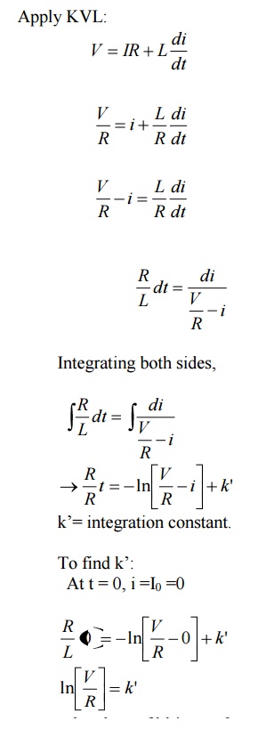
The response or the output of the series RL and RC circuits driven
dc excitations is called step response of the network.
Consider
that a dc voltage is applied to any general network through a switch k as shown
in fig.
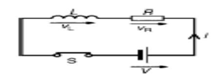
Initially switch k is kept open for very long time. So no voltage
is applied to the network. Thus the voltage at input-terminals of network is
zero. So we can write voltage across terminals A and B V
(l) is
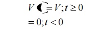
zero. When the switch k is closed at t=0, the dc voltage v gets applied to the
network. The voltage across terminals A and B suddenly or instantaneously rises
to voltage V. the variation of voltage across terminals +1 and B against time t
as shown in fig (b).
In fig (b) it is observed that at t=0, there is a step of V volts.
Such signal or function is called step function. We can define step function as
When the
magnitude of the voltage applied is 1 volt then the function is called unit
step function.
When the circuits are driven
by driving sources, then such circuits are called driven circuits. When the
circuits are without such driving sources, then such circuits are called
undriven circuits or
source
free circuits.
Step response of Driver series RL circuit:-
Consider
a series RL circuit.
At t=0-, switch k is about to close
but not fully closed. As voltage is not applied to the circuit, current in the
circuit will be zero.
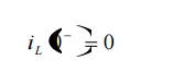
In this current through inductor can not change instantaneously.
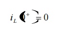
Let initial current through inductor can be
represented as I0. in above case I0 is zero. Assume that
switch k is closed at t =0.
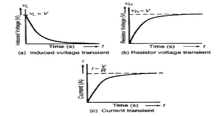
From above fig (a) shows variation of current I with respect to
time (t) i.e. current increases exponentially with respect to time. The rising
current produces rising flux, which induces emf in coil. According to Lens’s
law, the self induced emf opposes the flow of current. Because of this induced
emf and its opposition, the current in the coil don’t reach its max value.
The point p shown on graph indicates that current in circuit rises
to 0.632 time’s maximum value of current in steady state.
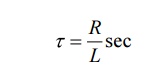
“the time required for the current to rise to
the 0.632 of its final value is known as time constant of given RL circuit. The
time constant is denoted by z”. Thus for series RL circuit, time constant is
The initial rate of rise of current is large up to first time
constant. At later stage, the rate of rise of current reduces.
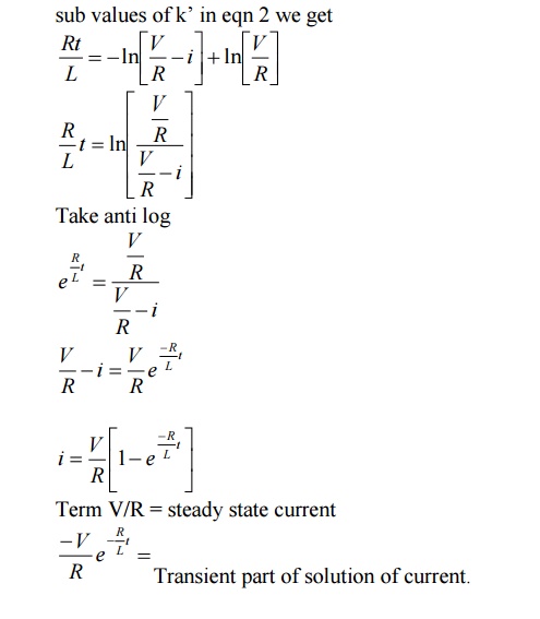
Theoretically I reach maximum value after
infinite time.
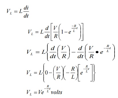
Voltage
across inductor L is given by
Related Topics