Chapter: Electrical and electronics : Circuit Theory : Resonance and Coupled Circuits
Solved Problems: Resonance and Coupled Circuits
Q. A pure inductance of 150 mH is connected in parallel with a 40 μF capacitor across a 50 V, variable frequency supply. Determine (a) the resonant frequency of the circuit and (b) the current circulating in the capacitor and inductance at resonance.
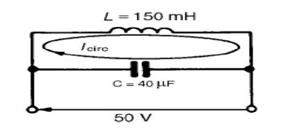
The circuit diagram is
shown in Figure 16.10.
(a) Parallel
resonant-R/L frequency,
However, resistance R =
0. Hence,
fr =
1/2π√1/LC
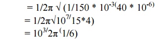
= 64.97
Hz
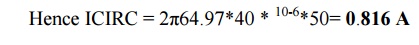
(b) Current circulating in L and C at resonance,
ICIRC = V/XC
=
V
/1/2πfrC
=
2πfrCV
Alternatively,
ICIRC = V/XL
=
V/2πfrL
=
50/2π64.9*0.15
= 0.817
A
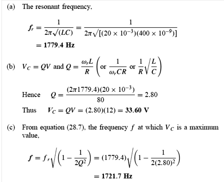
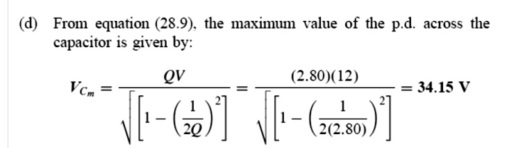
Q. 1- A series L–R–C circuit has a sinusoidal input voltage of maximum value 12 V. If inductance, L = 20 mH, resistance, R = 80 Ω, and capacitance, C = 400 nF, determine (a) the resonant frequency, (b) the value of the p.d. across the capacitor at the resonant frequency, (c) the frequency at which the p.d. across the capacitor is a maximum, and (d) the value of the maximum voltage across the capacitor.
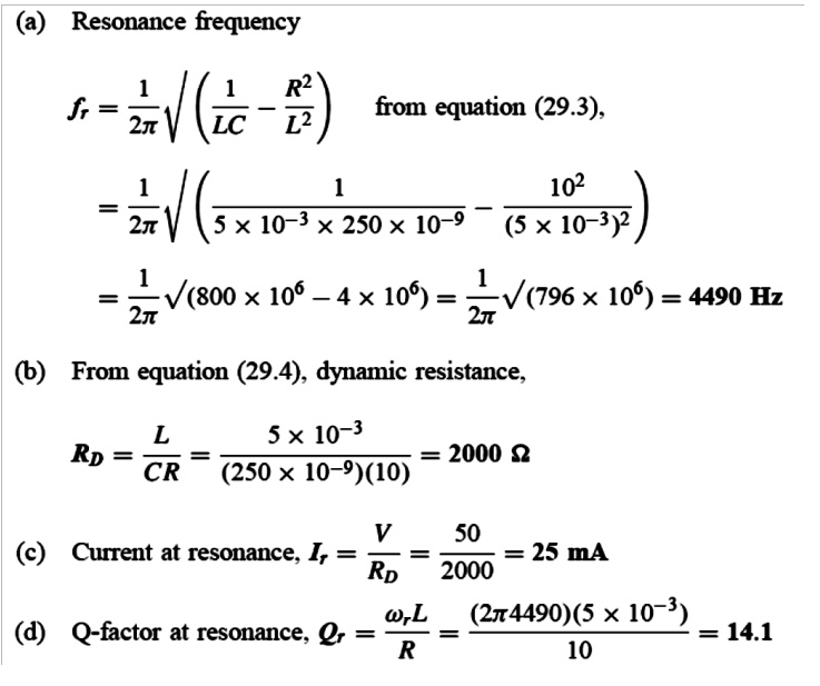
Q- A coil of inductance
5 mH and resistance 10 Ω is connected in parallel with a 250 nF capacitor across a 50 V
variable-frequency supply. Determine (a) the
resonant frequency, (b) the dynamic resistance, (c) the current at
resonance, and (d) the circuit Q-factor at resonance.
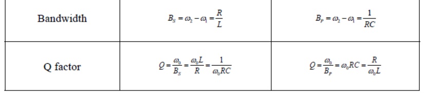
Summary of the properties of RLC resonant circuits.
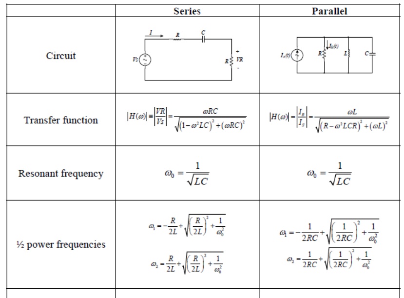
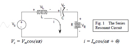
Series Resonance
The basic series-resonant circuit is shown in fig. 1. Of interest here in how the steady state amplitude and the phase angle of the current vary with the frequency of the sinusoidal voltage source. As the frequency of the source changes, the maximum amplitude of the source voltage (Vm) is held constant
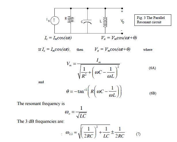
Parallel Resonance:
The basic parallel-resonant circuit is shown in fig. 3. Of interest here in how the steady state amplitude and the phase angle of the output voltage V0 vary with the frequency of the sinusoidal voltage source.
Related Topics