Chapter: Electrical and electronics : Circuit Theory : Resonance and Coupled Circuits
Important Short Questions and Answers: Resonance and Coupled Circuits
1. Define resonance. What is the condition for resonance for an RLC series circuit?
A circuit is said to be in resonance when the applied voltage and current are in phase. For an RLC series circuit, at resonance the inductive and capacitive reactance are equal.
2. How the RLC series circuit behaves for the frequencies above and below the resonant frequencies.
For frequencies below resonant frequency, the capacitive reactance is more than the inductive reactance. Therefore the equivalent reactance is equal to capacitive and the circuit behaves like a RC circuit.
For frequencies above resonant frequency, the inductive reactance is more than the capacitive reactance. Therefore the equivalent reactance is equal to inductive and the circuit behaves like a RL circuit.
3. Derive the expression for resonant frequency.
At resonance condition, the inductive and capacitive reactances are equal.
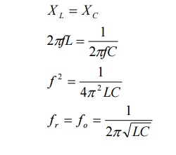
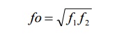
4. Define resonant frequency
The frequency at resonance is called as resonant frequency.
It is also defined as the geometric mean of two half power frequencies is called resonant frequency.
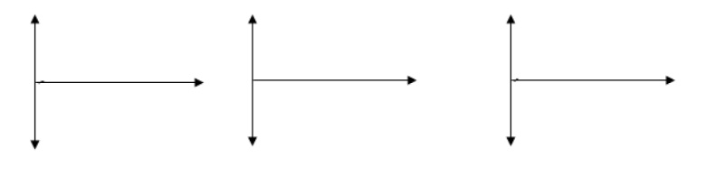
5. Draw the phasor diagrams for series RLC circuit.
6. Draw the curves for variation of impedance, admittance and current with frequency in RLC series resonance circuit.
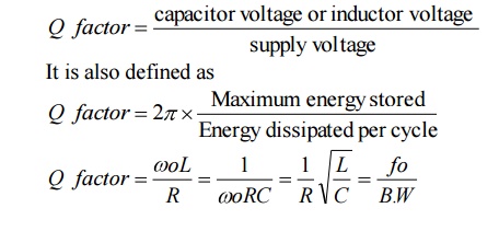
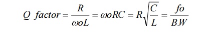
7. Define Q factor
It is the ratio between capacitor voltage or inductor voltage at resonance to supply voltage is called as Q-factor or quality factor.
8. Define Bandwidth.
It is defined as the width of the resonant curve upto frequency at which the power in the circuit is half of its maximum value. The difference between two half power frequencies is also called as band width.
9. Define selectivity.
It is the ratio of bandwidth to resonant frequency.
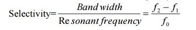
Selectivity of a resonant circuit is its ability to discriminate between signals of desired and undesired frequencies.
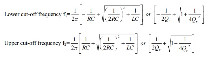
10. Define half power frequencies.
The frequencies at which the power in the circuit is half of its maximum value are called as half power frequencies.
f1=lower cut-off frequency
f2=upper cut-off frequency
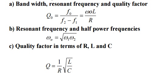
11.Give the relationship between
Band width, resonant frequency and quality factor
b) Resonant frequency and half power frequencies
c) Quality factor in terms of R, L and C
12. In series resonance circuit, on resonance the following will occur
V=VR,
XL=XC,
Z=R,
VL=VC
13. What inductance will give the same reactan
The inductive and capacitive reactances are same
14. A series resonant circuit is capacitive at f=150 HZ, The circuit will be inductive some where at
a) f greater than 150HZ
b) f equal to 150HZ
c) f less than 150HZ
d) None of the above ANS: f greater than 150HZ
15.A series RLC circuit has R=50Ω;L=100μH;and resonance?
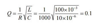
16.An RLC circuit consists of a resistance of 1000W,an inductance of 100 mH and a capacitance of 10μF.The Q factor of the circuit is
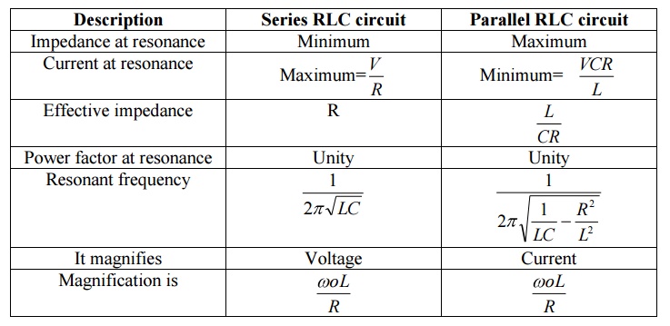
17. Write the characteristics of series resonance.
A series RLC circuit, at resonance condition
i) The power factor is unity
ii) Impedance of the circuit is minimum
iii) Admittance of the circuit is maximum
iv) Current is maximum
v)The magnitude of the voltage across inductance and capacitance will be Q times the supply voltage, but they are in phase opposition.
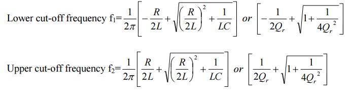
18. Write the expression for half power frequencies of RLC series circuit.
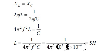
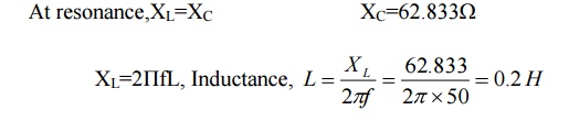
19. 19. An RLC series circuit has R=10Ω,XC=62.833 Ω.Find the value of L for resonance at 50HZ.
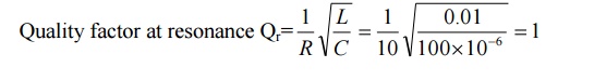
20. Determine the quality factor of the RLC serious.
Quality factor at resonance Qr
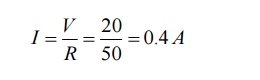
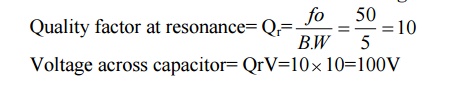
21. A series RLC circuit is excited with 10V sinusoidal source resonate at a frequency of 50HZ.If the bandwidth is 5HZ.What will the voltage across capacitance?
Quality factor at resonance= Qr
Voltage across capacitor= QrV
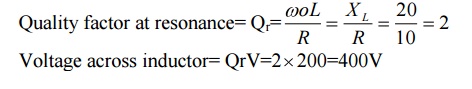
22. 22. A series RLC circuit has R=10Ω,XC=20 Ω and XL=20 Ω is excited by a sinusoidal source of voltage 200V.What will the voltage across inductance.
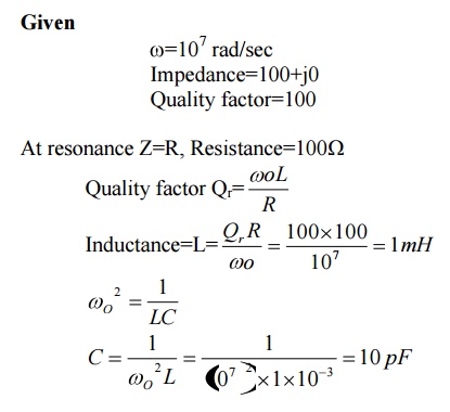
23. The impedance and quality factor of a RLC series circuit at =107 rad/sec are 100+j0 and 100 respectively. Find the values of R, L and C.
24. What is anti resonance?
In RLC parallel circuit, the current is minimum at resonance whereas in series resonance the current is maximum. Therefore the parallel resonance is called anti-resonance.
25. Write the expressions for quality factor of parallel RLC circuit.
26. Write the expression for half power frequencies of parallel RLC circuit.
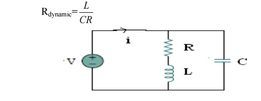
27. What is dynamic resistance? Write the expression for dynamic resistance of RL circuit parallel with C.
The resistance of the RLC parallel circuit at resonance is called dynamic resistance.
28.Write the characteristics of parallel resonance.
i) At resonance, admittance is minimum and equal to conductance, therefore current is minimum.
ii) Below resonant frequency, the circuit behaves as inductive circuit and above resonant frequency, the circuit behaves as capacitive circuit.
iii) At resonance, the magnitude of current through inductance and capacitance will be Q times the current supplied by the source, but they are in phase opposition.
28.Draw the curves for variation of impedance, admittance and current with frequency in RLC parallel resonance circuit.
30. Compare the series and parallel resonant circuit.(consider practical parallel resonant circuit)
31. Why is a series resonance circuit regarded as acceptor circuit?
A series resonance circuit has a capability to draw heavy currents and power from the mains. So it is regarded as acceptor circuit.
32. Why is a parallel resonance circuit regarded as rejecter circuit?
A parallel resonance circuit has a capability to very small currents and power from the mains. So it is regarded as rejecter circuit.
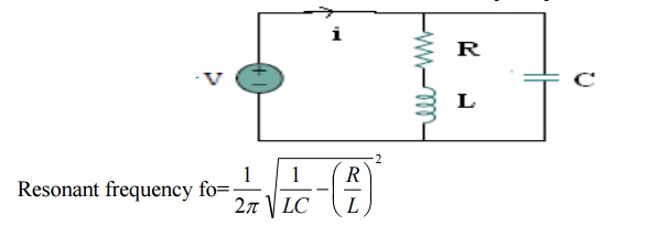
33. A coil of resistance R, an inductance L is shunted by a capacitor C and this parallel combination is under resonance. What is the resonate frequency of the circuit?
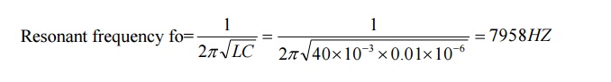
34. Find the resonant frequency in the ideal parallel RLC circuit with L=40 mH and c=0.01μF.
35. Draw the two branch parallel resonant circuit.
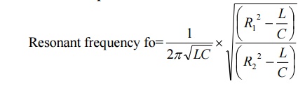
Resonant frequency fo
36. What is the nature of power factor if the frequency of operation is less than the resonance frequency in a RLC series circuit?
When the frequency is less than resonance frequency fo, the current lags behind the voltage.i.e.,φ is leading in nature.Hence,the resonance frequency.
37. Draw the variation of reactance with frequency in series resonance circuit.
38. Draw the variation of susceptance with frequency in parallel resonance circuit
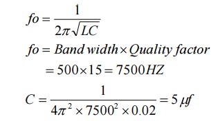
39.A series RLC circuit has a bandwidth of 500HZ.The quality factor is 15.If the value of L is 0.02.Find the value of C.
40. What is magnetic coupling?
When two coils are placed close to each other, magnetic flux produced in one coil will be linking partially or fully with the other coil. This is called magnetic coupling.
41. Define induced emf.
It is the property of electromagnetic fields that whenever a coil has an alternating current passed through it, an emf is induced in it due to the alternating magnetic field surrounding the coil. Types of induced emf
(i) Self induced emf
(ii) Mutually induced emf
42. Define self induced emf.
When an alternating current is passed through a coil, an alternating magnetic field is set up, which surrounds the coil. This induced emf is called self induced emf.It is so called because emf is induced due to its own magnetic field.
43. Define mutually induced emf.
When two coils are placed very close to each other. an emf is induced in the other coil also, which is called mutually induced emf.
44. Define inductance.
It is defined as the flux linkages per unit current. There are two types of inductance.
(i) Self inductance
(ii) Mutual inductance
45. Define self inductance.
Self inductance of a coil is defined as the flux linkages per unit current flowing through the coil. Its unit is Henry.
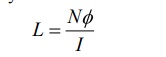
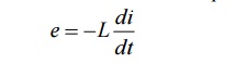
The self induced emf in a coil can be expressed in terms of self inductance.
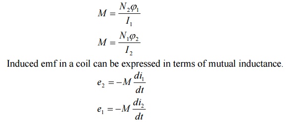
46.Define mutual inductance.
Mutual inductance between two coils is defined as the flux linkages in one coil due to unit current in other coil. Its unit is Henry.
47. What are coupled circuits?
The coupled coils refer to circuits involving elements with magnetic coupling. If the flux produced by an element of a circuit links other elements of the same circuit or near-by circuit then the elements are said to have magnetic coupling.
48. What are coupled coils?
When two or more coils are linked by magnetic flux. then the coils are called coupled coils(or the coupled coils are group of two or more coils linked by magnetic flux)
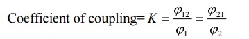
49. Define coefficient of coupling.
In coupled coils, the coefficient of coupling is defined as then fraction of the total flux produced by one coil linking another coil.
50.What is dot convention? Why it is required?
The sign or polarity of mutually induced emf depends on the winding sense (or coil orientation) and current through the coil. The winding sense is decided by the manufacturer and to inform the user about the winding sense a dot is placed at one end/terminal of each coil. When current enter at dotted end in one coil then the mutual induced emf in the other coil is positive at dot end. Hence the dot convention is required to predict the sign of mutually induced emf.
51. State Dot rule for coupled circuits.
If current enters into the dots of both the coils or out of dots of both the coils, then the mutually induced voltages for both the coils are having the same polarity of self induced voltages.
If current enter into (or out of) the dot in one coil and in other coil current flows out of (or into) the dot, then the mutually induced voltage will have polarity opposite to that of self induced voltages.
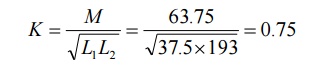
52. Two coupled coils have a self inductances 37.5 mH and 193 mH,with the mutual inductance of 63.75 mH.Find the co efficient of coupling.
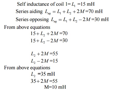
54. A 15 mH coil is connected in series with another coil. The total inductance is 70 mH.When one of the coils is reversed, the total inductance is 30 mH.Find the self inductance of second coil, mutual inductance and coefficient of coupling.
Given:
Self inductance of coil 1= L1 =15 mH
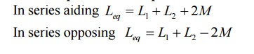
55. Write the expression for equivalent inductance of two coupled coils connected in series.
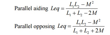
56. Write the expression for equivalent inductance of two coupled coils connected in parallel.
57. Write the relation between self and mutual inductance
L1=Self inductance of coil 1
L2=Self inductance of coil 2
K=Co efficient of coupling
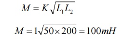
58. What is the maximum possible mutual inductance of two inductively coupled coils with self inductances of 50mH and 200 mH?
L1=50mH
L2=200 mH
K=1 for max M
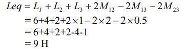
59.59. Find the equivalent inductance of the circuit shown.
59.What is tuned coupled circuit?
In a coupled circuit, when capacitors are added to primary and secondary of coupled coils to resonate the coils to achieve maximum power transfer condition, then the coupled circuit is called tuned coupled circuit.
61. Why and where the tuned coupled circuits are employed?
The tuned coupled circuits are mainly used to transfer energy from a weak source to a load or employed for maximum power transfer from one circuit to another circuit. This is possible only when both coils work at resonance condition.
62. What is single tuned circuit?
In a coupled circuit, when capacitors are added to secondary coil to resonate the secondary, the coupled circuit is called single tuned coupled circuit.
63. What is double tuned circuit?
In a coupled circuit, when capacitors are added both primary and secondary coils to resonate the primary and secondary, the coupled circuit is called double tuned coupled circuit.
Related Topics