Chapter: Microprocessor and Microcontroller
Interface of 8051
Serial Interface
The
serial port of 8051 is full duplex, i.e., it can transmit and receive
simultaneously.
The
register SBUF is used to hold the data. The special function register SBUF is
physically two registers. One is, write-only and is used to hold data to be
transmitted out of the 8051 via TXD. The other is, read-only and holds the
received data from external sources via RXD. Both mutually exclusive registers
have the same address 099H.
Serial Port Control Register (SCON)
Register
SCON controls serial data communication.
Address:
098H (Bit addressable)
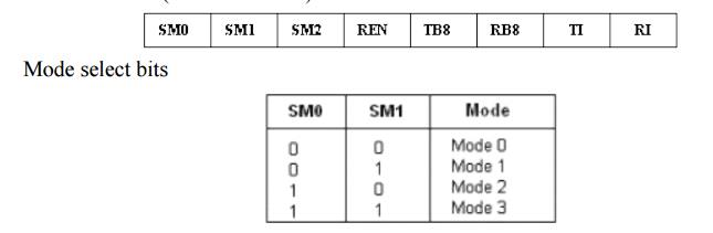
SM2:
multi processor communication bit REN: Receive enable bit
TB8:
Transmitted bit 8 (Normally we have 0-7 bits transmitted/received) RB8:
Received bit 8
TI:
Transmit interrupt flag RI: Receive interrupt flag
Power Mode control Register
Register
PCON controls processor powerdown, sleep modes and serial data bandrate. Only
one bit of PCON is used with respect to serial communication. The seventh bit
(b7)(SMOD) is used to generate the baud rate of serial communication.
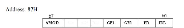
SMOD:
Serial baud rate modify bit GF1: General purpose user flag bit 1 GF0: General
purpose user flag bit 0 PD: Power down bit
IDL: Idle
mode bit
Data Transmission
Transmission
of serial data begins at any time when data is written to SBUF. Pin P3.1
(Alternate function bit TXD) is used to transmit data to the serial data
network. TI is set to 1 when data has been transmitted. This signifies that
SBUF is empty so that another byte can be sent.
Data Reception
Reception
of serial data begins if the receive enable bit is set to 1 for all modes. Pin
P3.0 (Alternate function bit RXD) is used to receive data from the serial data
network. Receive interrupt flag, RI, is set after the data has been received in
all modes. The data gets stored in SBUF register from where it can be read.
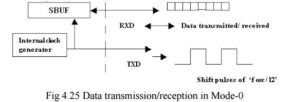
Serial Data Transmission Modes:
Mode-0: In this mode, the serial port works
like a shift register and the data transmission works synchronously with a
clock frequency of fosc /12. Serial data is received and transmitted
through RXD. 8 bits are transmitted/ received aty a time. Pin TXD outputs the
shift clock pulses of frequency fosc /12, which is connected to the
external circuitry for synchronization. The shift frequency or baud rate is
always 1/12 of the oscillator frequency.
Mode-1 (standard
UART mode) :
In
mode-1, the serial port functions as a standard Universal Asynchronous Receiver
Transmitter (UART) mode. 10 bits are transmitted through TXD or received
through RXD. The 10 bits consist of one start bit (which is usually '0'), 8
data bits (LSB is sent first/received first), and a stop bit (which is usually
'1'). Once received, the stop bit goes into RB8 in the special function
register SCON. The baud rate is variable.
The
following figure shows the way the bits are transmitted/ received.
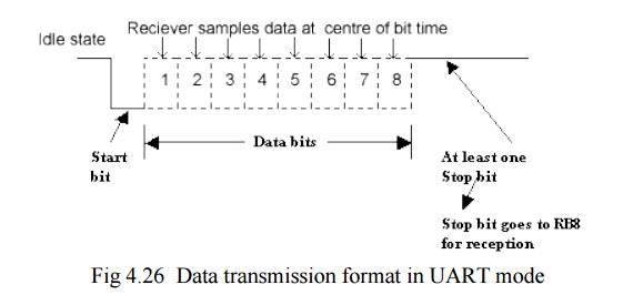
Bit time=
1/fbaud
In
receiving mode, data bits are shifted into the receiver at the programmed baud
rate. The data word (8-bits) will be loaded to SBUF if the following conditions
are true.
1. RI must
be zero. (i.e., the previously received byte has been cleared from SBUF)
2. Mode bit
SM2 = 0 or stop bit = 1.
After the
data is received and the data byte has been loaded into SBUF, RI becomes one.
Mode-1
baud rate generation:
Timer-1
is used to generate baud rate for mode-1 serial communication by using overflow
flag of the timer to determine the baud frequency. Timer-1 is used in timer
mode-2 as an auto-reload 8-bit timer. The data rate is generated by timer-1
using the following formula.
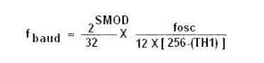
Where,
SMOD is
the 7th bit of PCON register
fosc
is the crystal oscillator frequency of the microcontroller
It can be
noted that fosc/ (12 X [256- (TH1)]) is the timer overflow frequency
in timer mode-2, which is the auto-reload mode.
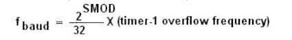
If
timer-1 is not run in mode-2, then the baud rate is,
Timer-1
can be run using the internal clock, fosc/12 (timer mode) or from any external
source via pin T1 (P3.5) (Counter mode).
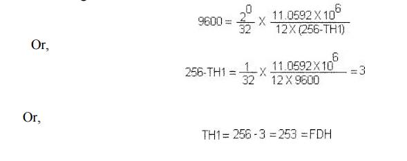
Example: If standard baud rate is desired,
then 11.0592 MHz crystal could be selected.
To get a standard 9600 baud rate, the setting of TH1 is calculated as
follows. Assuming SMOD to be '0'
In
mode-1, if SM2 is set to 1, no receive interrupt (RI) is generated unless a
valid stop bit is received.
Serial Data Mode-2 - Multiprocessor Mode :
In this
mode 11 bits are transmitted through TXD or received through RXD. The various
bits are as follows: a start bit (usually '0'), 8 data bits (LSB first), a
programmable 9 th (TB8 or RB8)bit and a stop bit (usually '1').
While
transmitting, the 9 th data bit (TB8 in SCON) can be assigned the
value '0' or '1'. For example, if the information of parity is to be
transmitted, the parity bit (P) in PSW could be moved into TB8. On reception of
the data, the 9 th bit goes into RB8 in 'SCON', while the stop bit
is ignored. The baud rate is programmable to either 1/32 or 1/64 of the
oscillator frequency.
f baud
= (2 SMOD /64) fosc.
Mode-3 - Multi processor mode with variable baud
rate :
In this
mode 11 bits are transmitted through TXD or received through RXD. The various
bits are: a start bit (usually '0'), 8 data bits (LSB first), a programmable 9
th bit and a stop bit (usually '1').
Mode-3 is
same as mode-2, except the fact that the baud rate in mode-3 is variable (i.e.,
just as in mode-1).
f baud
= (2 SMOD /32) * ( fosc / 12 (256-TH1)) . This baudrate
holds when Timer-1 is programmed in Mode-2.
Related Topics