Chapter: Microprocessor and Microcontroller : 8086 Microprocessor
8086-Minimum mode of operation
8086-Minimum mode of operation
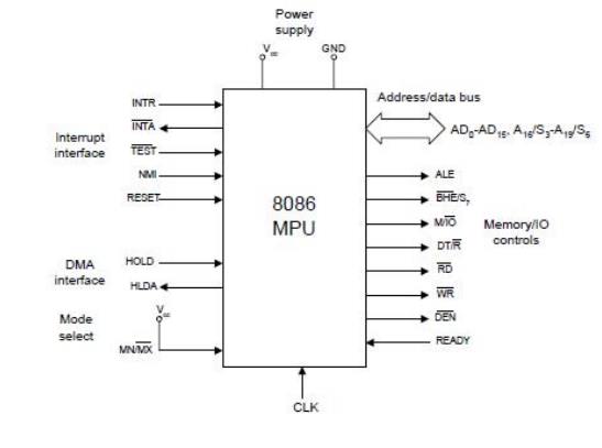
1 Minimum Mode Interface
ü Address/Data bus: 20 bits
vs 8 bits multiplexed
ü Status signals: A16-A19 multiplexed with status
signals S3-S6 respectively
a. S3 and S4
together form a 2 bit binary code that identifies which of the internal segment
registers was used to generate the physical address that was output on the
address bus during the current bus cycle.
b. S5 is the
logic level of the internal interrupt enable flag, s6 is always logic 0.
Control Signals:
ü Address Latch Enable (ALE) is a
pulse to logic 1 that signals external circuitry when a valid address is on the bus. This address
can be latched in external circuitry on the 1-to-0 edge of the pulse at ALE.
ü IO/M line: memory or I/O transfer is
selected (complement for 8086)
ü DT/R line: direction of data is selected
ü SSO (System Status Output) line: =1 when
data is read from memory and =0 when code is read from memory (only for 8088)
ü BHE (Bank High Enable) line : =0 for
most significant byte of data for 8086 and also carries S7
ü RD line: =0 when a read cycle is in
progress
ü WR line: =0 when a write cyle is in
progress
ü DEN line: (Data enable) Enables
the external devices to supply data to the processor.
ü Ready line: can be used to insert wait states
into the bus cycle so that it is extended by a number of clock periods
Interrupt signals:
ü INTR (Interrupt request) :=1 shows
there is a service request, sampled at the final clock cycle of each instruction acquisition cycle.
ü INTA : Processor responds with two
pulses going to 0 when it services the interrupt and waits for the interrupt service number after the second pulse.
ü TEST: Processor suspends operation
when =1. Resumes operation when=0. Used to syncronize the processor to external events.
ü NMI (Nonmaskable interrupt) : A leading
edge transition causes the processor go to the interrupt routine after the current instruction is executed.
ü RESET : =0 Starts the reset sequence.
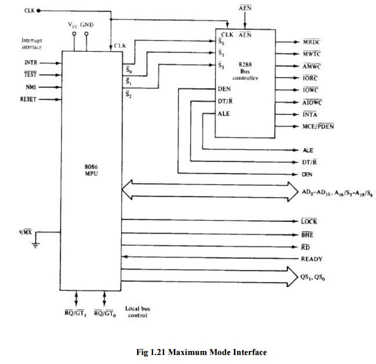
2 Maximum Mode Interface
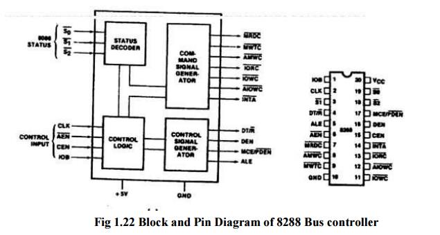
ü For
multiprocessor environment 8288 Bus Controller is used for bus control
ü WR¯
,IO/M¯ ,DT/R¯ ,DEN¯ ,ALE, INTA¯ signals are not available
ü Instead
a. MRDC¯ (memory read command)
b. MWRT¯ (memory write command)
c. AMWC¯ (advanced memory write command)
d. IORC¯ (I/O read command)
e. IOWC¯ (I/O write command)
f. AIOWC¯ (Advanced I/O write command)
g. INTA¯ (interrupt acknowledge)
ü The
signals shown above are produced by 8288 depending on the state of S0, S1 and
S2.
a. DEN, DT/R¯ and ALE signals are the same as
minimum-mode systems
b. LOCK¯ : when =0, prevents other
processors from using the bus
c. QS0 and QS1 (queue status signals): informs
about the status of the queue
d. RQ¯ /GT ¯ 0 and RQ¯ /GT ¯ 1 are used instead of HOLD and HLDA lines in a multiprocessor environment as
request/grant lines.
Related Topics