Chapter: Microprocessor and Microcontroller : 8086 Microprocessor
Interrupts and Interrupt Routines in 8086 Microprocessor
Interrupts And Interrupt Routines
1) Interrupt and its Need:
The
microprocessors allow normal program execution to be interrupted in order to
carry out a specific task/work. The processor can be interrupted in the
following ways
i) by an
external signal generated by a peripheral,
ii) by an
internal signal generated by a special instruction in the program,
iii) by an
internal signal generated due to an exceptional condition which occurs while
executing an instruction. (For example, in 8086 processor, divide by zero is an
exceptional condition which initiates type 0 interrupt and such an interrupt is
also
called
execution).
The
process of interrupting the normal program execution to carry out a specific
task/work is referred to as interrupt. The interrupt is initiated by a signal
generated by an external device or by a signal generated internal to the
processor.
When a
microprocessor receives an interrupt signal it stops executing current normal
program, save the status (or content) of various registers (IP, CS and flag
registers in case of 8086) in stack and then the processor executes a
subroutine/procedure in order to perform the specific task/work requested by
the interrupt. The subroutine/procedure that is executed in response to an
interrupt is also called Interrupt Service Subroutine (ISR). At the end of ISR,
the stored status of registers in stack is restored to respective registers,
and the processor resumes the normal program execution from the point
{instruction) where it was interrupted.
The
external interrupts are used to implement interrupt driven data transfer
scheme. The interrupts generated by special instructions are called software
interrupts and they are used to implement system services/calls (or monitor
services/calls). The system/monitor services are procedures developed by system
designer for various operations and stored in memory. The user can call these
services through software interrupts. The interrupts generated by exceptional
conditions are used to implement error conditions in the system.
2) Interrupt Driven Data Transfer Scheme
The
interrupts are useful for efficient data transfer between processor and
peripheral. When a peripheral is ready for data transfer, it interrupts the
processor by sending an appropriate signal. Upon receiving an interrupt signal,
the processor suspends the current program execution, save the status in stack
and executes an ISR to perform the data transfer between the peripheral and
processor.
At the
end of ISR the processor status is restored from stack and processor resume its
normal program execution. This type of data transfer scheme is called interrupt
driven data transfer scheme.
The data
transfer between the processor and peripheral devices can be implemented either
by polling technique or by interrupt method. In polling technique, the
processor has to periodically poll or check the status/readiness of the device
and can perform data transfer only when the device 'is ready. In polling
technique the processor time is wasted, because the processor has to suspend
its work and check the status of the device in predefined intervals.
If the
device interrupts the processor to initiate a data transfer whenever it is
ready then the processor time is effectively utilized because the processor
need not suspend its work and check the status of the device in predefined
intervals.
For an
example, consider the data transfer from a keyboard to the processor. Normally
a keyboard has to be checked by the processor once in every 10 milliseconds for
a key press. Therefore once in every 10 milliseconds the processor has to
suspend its work and then check the keyboard for a valid key code.
Alternatively, the keyboard can interrupt the processor, whenever a key is
pressed and a valid key code is generated. In this way the processor need not
waste its time to check the keyboard once in every 10 milliseconds.
3) Classification of Interrupts
In
general the interrupts can be classified in the following three ways:
1. Hardware
and software interrupts
2. Vectored
and Non Vectored interrupt:
3. Maskable
and Non Maskable interrupts.
The
interrupts initiated by external hardware by sending an appropriate signal to
the interrupt pin of the processor is called hardware interrupt. The 8086
processor has two interrupt pins INTR and NMI. The interrupts initiated by
applying appropriate signal to these pins are called hardware interrupts of
8086.
The
software interrupts are program instructions. These instructions are inserted
at desired locations in a program. While running a program, if software
interrupt instruction is encountered then the processor initiates an interrupt.
The 8086 processor has 256 types of software interrupts. The software interrupt
instruction is INT n, where n is the type number in the range 0 to 255.
When an
interrupt signal is accepted by the processor, if the program control
automatically branches to a specific address (called vector address) then the
interrupt is called vectored interrupt. The automatic branching to vector
address is predefined by the manufacturer of processors. (In these vector
addresses the interrupt service subroutines (ISR) are stored). In non-vectored
interrupts the interrupting device should supply the address of the ISR to be
executed in response to the interrupt. All the 8086 interrupts are vectored
interrupts. The vector address for an 8086 interrupt is obtained from a vector
table implemented in the first 1kb memory space (00000h to 03FFFh).
The
processor has the facility for accepting or rejecting hardware interrupts.
Programming the processor to reject an interrupt is referred to as masking or
disabling and programming the processor to accept an interrupt is referred to
as unmasking or enabling. In 8086 the interrupt flag (IF) can be set to one to
unmask or enable all hardware interrupts and IF is cleared to zero to mask or
disable a hardware interrupts except NMI.
The interrupts whose request can be either accepted
or rejected by the processor are called maskable interrupts. The interrupts
whose request has to be definitely accepted (or cannot be rejected) by the
processor are called non-maskable interrupts. Whenever a request is made by
non-maskable interrupt, the processor has to definitely accept that request and
service that interrupt by suspending its current program and executing an ISR.
In 8086 processor all the hardware interrupts initiated through INTR pin are
maskable by clearing interrupt flag (IF). The interrupt initiated through NMI
pin and all software interrupts are non-maskable.
4) Sources of Interrupts in 8086
An
interrupt in 8086 can come from one of the following three sources.
1. One
source is from an external signal applied to NMI or INTR input pin of the
processor. The interrupts initiated by applying appropriate signals to these
input pins are called hardware interrupts.
2. A second
source of an interrupt is execution of the interrupt instruction "INT
n", where n is the type number. The interrupts initiated by "INT
n" instructions are called software interrupts.
3. The third
source of an interrupt is from some condition produced in the 8086 by the
execution of an instruction. An example of this type of interrupt is divide by
zero interrupt. Program execution will be automatically interrupted if you
attempt to divide an operand by zero. Such conditional interrupts are also known
as exceptions.
5) Interrupts of 8086
The 8086
microprocessor has 256 types of interrupts. INTEL has assigned a type number to
each interrupt. The type numbers are in the range of 0 to 255. The 8086
processor has dual facility of initiating these 256 interrupts. The interrupts
can be initiated either by executing "INT n" instruction where n is
the type number or the interrupt can be initiated by sending an appropriate
signal to INTR input pin of the processor.
For the
interrupts initiated by software instruction" INT n ", the type
number is specified by the instruction itself. When the interrupt is initiated
through INTR pin, then the processor runs an interrupt acknowledge cycle to get
the type number. (i.e., the interrupting device should supply the type number
through D0- D7 lines when the processor requests for the same through interrupt
acknowledge cycle).
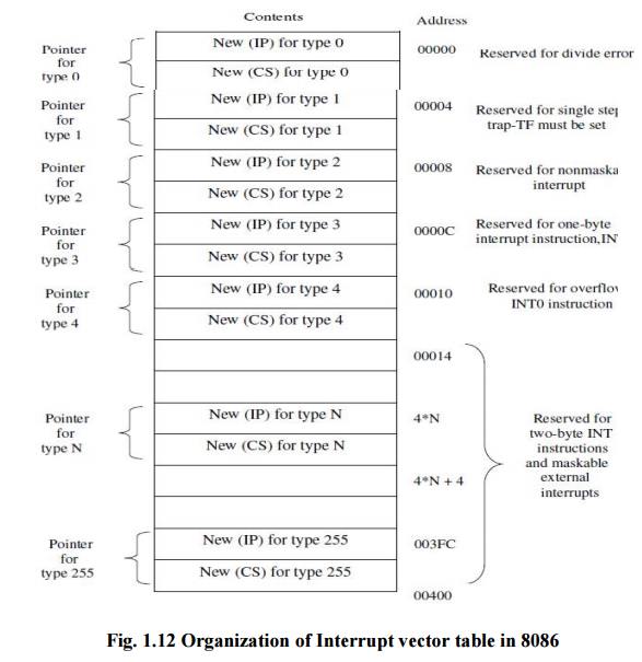
Only the first five types have explicit definitions; the other types may be used by interrupt instructions or external interrupts. From the figure it is seen that the type associated with a division error interrupt is 0. Therefore, if a division by 0 is attempted, the processor will push the current contents of the PSW, CS and IP into the stack, fill the IP and CS registers from the addresses 00000 to 00003, and continue executing at the address indicated by the new contents of IP and CS. A division error interrupt occurs any time a DIV or IDIV instruction is executed with the quotient exceeding the range, regardless of the IF (Interrupt flag) and TF (Trap flag) status.
The type
1 interrupt is the single-step interrupt (Trap interrupt) and is the only
interrupt controlled by the TF flag. If the TF flag is enabled, then an
interrupt will occur at the end of the next instruction that will cause a
branch to the location indicated by the contents of 00004H to 00007H.The single
step interrupt is used primarily for debugging which gives the programmer a
snapshot of his program after each instruction is executed
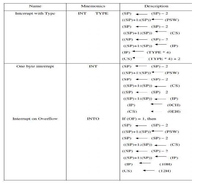
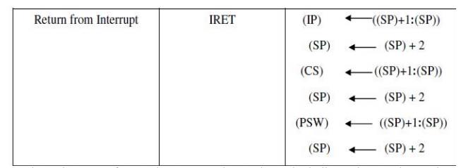
IRET is
used to return from an interrupt service routine. It is similar to the RET
instruction except that it pops the original contents of the PSW from the stack
as well as the return address. The INT instruction has one of the forms
INT or
INT Type
The INT
instruction is also often used as a debugging aid in cases where single
stepping provides more detail than is wanted.
By inserting
INT instructions at key points, called breakpoints.
Within a program a programmer can use an interrupt routine to provide messages
and other information at these points. Hence the 1 byte INT instruction (Type 3
interrupt) is also referred to as breakpoint
interrupt.
The INTO
instruction has type 4 and causes an interrupt if and only if the OF flag is
set to 1. It is often placed just after an arithmetic instruction so that
special processing will be done if the instruction causes an overflow. Unlike a
divide-by-zero fault, an overflow condition does not cause an interrupt
automatically; the interrupt must be explicitly specified by the INTO
instruction. The remaining interrupt types correspond to interrupts
instructions imbedded in the interrupt program or to external interrupts.
Related Topics