Chapter: Microprocessor and Microcontroller : 8051 Micro Controller
Interrupt Structure - 8051 Micro Controller
Interrupt Structure
ü 8051
provides 4 interrupt sources
1. 2 external
interrupts
2. 2 timer
interrupts
ü They are
controlled via two SFRs, IE and IP
ü Each
interrupt source can be individually enabled or disabled by setting or clearing
a bit in IE (Interrupt Enable). IE also exists a global disable bit, which can
be cleared to disable all interrupts at once
ü Each
interrupt source can also be individually set to one of two priority levels by
setting or clearing a bit in IP (Interrupt Priority)
ü A
low-priority interrupt can be interrupted by high-priority interrupt, but not
by another low-priority one
ü A
high-priority interrupt can‟t be interrupted by any other interrupt source
ü If
interrupt requests of the same priority level are received simultaneously, an
internal polling sequence determines which request is serviced, so within each
priority lever there is a second priority structure
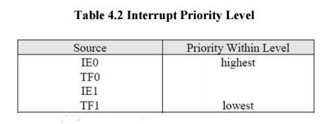
ü This
internal priority structure is determined by the polling sequence, shown in the
following table
1 External Interrupt
ü External
interrupts ~INT0 and ~INT1 have two ways of activation
1. Level-activated
2. Transition-activated
ü This
depends on bits IT0 and IT1 in TCON
ü The flags
that actually generate these interrupts are bits IE0 and IE1 in TCON
ü On-chip
hardware clears that flag that generated an external interrupt when the service
routine is vectored to, but only if the interrupt was transition-activated
ü When the
interrupt is level-activated, then the external requesting source is
controlling the request flag, not the on-chip hardware
2 Handling Interrupt
ü When
interrupt occurs (or correctly, when the flag for an enabled interrupt is found
to be set (1)), the interrupt system generates an LCALL to the appropriate
location in Program Memory, unless some other conditions block the interrupt
ü Several
conditions can block an interrupt
ü An
interrupt of equal or higher priority level is already in progress
ü The
current (polling) cycle is not the final cycle in the execution of the
instruction in progress
ü The
instruction in progress is RETI or any write to IE or IP registers
ü If an
interrupt flag is active but not being responded to for one of the above
conditions, must be still active when the
blocking condition is removed, or the denied interrupt will not be serviced
ü Next step
is saving the registers on stack. The hardware-generated LCALL causes only the
contents of the Program Counter to be pushed onto the stack, and reloads the PC
with the beginning address of the service routine
ü In some
cases it also clears the flag that generated the interrupt, and in other cases
it doesn‟t. It
clears an
external interrupt flag (IE0 or IE1) only if it was transition- avtivated.
ü Having
only PC be automatically saved gives programmer more freedom to decide how much time to spend saving other registers. Programmer must also be more
careful with proper selection, which register to save.
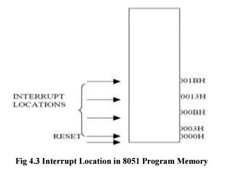
The service routine for each interrupt begins at a
fixed location. The interrupt locations are spaced at 8-byte interval,
beginning at 0003H for External Interrupt 0, 000BH for Timer 0, 0013H for
External Interrupt 1 and 001BH for Timer 1.
Related Topics