Chapter: Microprocessor and Microcontroller : 8051 Micro Controller
Timers - 8051 Micro Controller
Timers
The 8051 comes equipped with two timers, both of which may be
controlled, set, read, and configured individually. The 8051 timers have three
general functions: 1) Keeping time and/or calculating the amount of time
between events, 2) Counting the events themselves, or 3) Generating baud rates
for the serial port.
One of the primary uses of timers is to measure
time. We will discuss this use of timers first and will subsequently discuss
the use of timers to count events. When a timer is used to measure time it is
also called an "interval timer" since it is measuring the time of the
interval between two events.
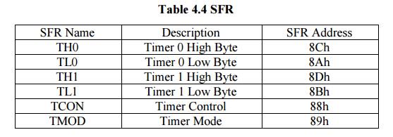
1Timer SFR
8051 has two timers which each function essentially
the same way. One timer is TIMER0 and the other is TIMER1. The two timers share
two SFRs (TMOD and TCON) which control the timers, and each timer also has two
SFRs dedicated solely to itself (TH0/TL0 and TH1/TL1).
2 13-bit Time Mode (mode 0)
Timer
mode "0" is a 13-bit timer. This is a relic that was kept around in
the 8051 to maintain compatability with its predecesor, the 8048. Generally the
13-bit timer mode is not used in new development.
When the
timer is in 13-bit mode, TLx will count from 0 to 31. When TLx is incremented
from 31, it will "reset" to 0 and increment THx. Thus, effectively,
only 13 bits of the two timer bytes are being used: bits 0-4 of TLx and bits
0-7 of THx. This also means, in essence, the timer can only contain 8192
values. If you set a 13-bit timer to 0, it will overflow back to zero 8192
machine cycles later.
Again,
there is very little reason to use this mode and it is only mentioned so you
wont be surprised if you ever end up analyzing archaeic code which has been
passed down through the generations (a generation in a programming shop is
often on the order of about 3 or 4 months).
3 16-bit Time Mode (mode 1)
Timer
mode "1" is a 16-bit timer. This is a very commonly used mode. It
functions just like 13-bit mode except that all 16 bits are used.
TLx is
incremented from 0 to 255. When TLx is incremented from 255, it resets to 0 and
causes THx to be incremented by 1. Since this is a full 16-bit timer, the timer
may contain up to
65536
distinct values. If you set a 16-bit timer to 0, it will overflow back to 0
after 65,536 machine cycles.
4 8-bit Time Mode (mode 2)
Timer
mode "2" is an 8-bit auto-reload mode. What is that, you may ask?
Simple. When a timer is in mode 2, THx holds the "reload value" and
TLx is the timer itself. Thus, TLx starts counting up. When TLx reaches 255 and
is subsequently incremented, instead of resetting to 0 (as in the case of modes
0 and 1), it will be reset to the value stored in THx.
5 Split Timer Mode (mode 3)
Timer mode "3" is a split-timer mode.
When Timer 0 is placed in mode 3, it essentially becomes two separate 8-bit
timers. That is to say, Timer 0 is TL0 and Timer 1 is TH0. Both timers count
from 0 to 255 and overflow back to 0. All the bits that are related to Timer 1
will now be tied to TH0.
While
Timer 0 is in split mode, the real Timer 1 (i.e. TH1 and TL1) can be put into
modes 0, 1 or 2 normally--however, you may not start or stop the real timer 1
since the bits that do that are now linked to TH0. The real timer 1, in this
case, will be incremented every machine cycle no matter what.
6 Using Timers As Event Counters
We've
discussed how a timer can be used for the obvious purpose of keeping track of
time. However, the 8051 also allows us to use the timers to count events.
How can
this be useful? Let's say you had a sensor placed across a road that would send
a pulse every time a car passed over it. This could be used to determine the
volume of traffic on the road. We could attach this sensor to one of the 8051's
I/O lines and constantly monitor it, detecting when it pulsed high and then
incrementing our counter when it went back to a low state. This is not terribly
difficult, but requires some code. Let's say we hooked the sensor to P1.0; the
code to count cars passing would look something like this:
JNB P1.0,
$ ; If a car hasn't raised the
signal, keep waiting
JB P1.0,
$ ; The line is high which means
the car is on the sensor right now
INC
COUNTER ; The car has passed completely,
so we count it
Related Topics