Chapter: Aquaculture Engineering : Water Transport
Head loss in single parts (fittings)
head loss in channels and pipe systems
Head loss in single
parts (fittings)
In addition to the head loss in the pipe there is energy
loss due to friction in pipe parts (fittings) because any obstructions in the
pipe which create extra turbulence will increase the head loss. Additional
turbulence occurs in the inlet and outlet of the pipe, in valves, bends,
reductions, connections, etc. The head loss can be calculated from the equation
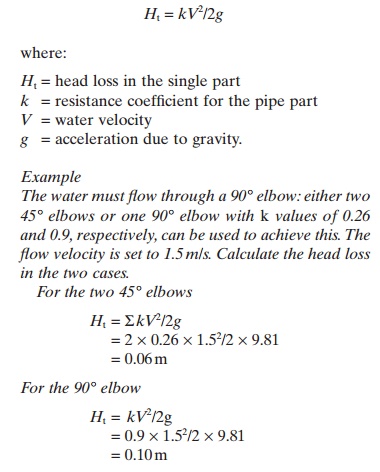
As this example
illustrates, there is a great advantage in using two 45° bends rather than one
90° bend to reduce the head loss. This will apply, for instance, for the outlet
pipe from a fish tank.
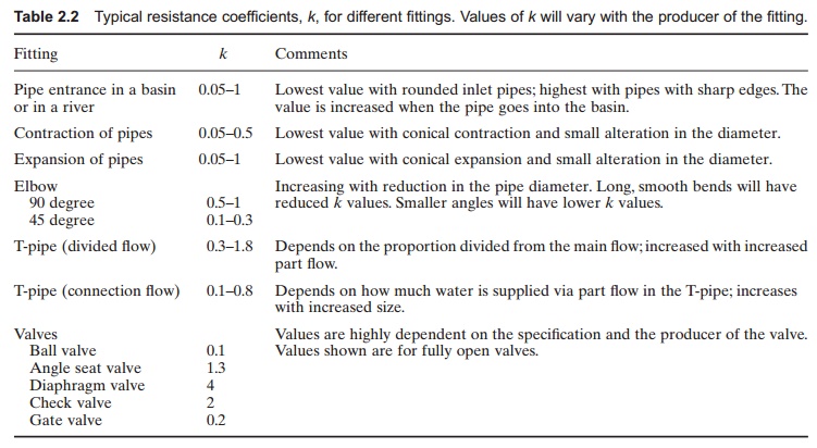
The k values for
different parts may be found from special tables (e.g. Table 2.2). They are
also found in catalogues published by suppliers of fittings.
When constructing the pipe system the head loss that
results from fittings in the pipeline must be considered in addition to the
head loss in the pipe itself. The resistance of every single part must be
added, so the sum of every single resistance plus the head loss in the pipeline
gives the total head loss.
When designing the inlet pipe to a fish farm, it is
important to use smooth bends to reduce the total head loss in the pipeline.
Related Topics