Chapter: Aquaculture Engineering : Water Transport
Head loss in pipelines
head loss in channels and pipe systems
Head loss in
pipelines
All transport of water through a pipe or a channel between
two points results in an energy loss (head loss). This is caused by friction
between the water molecules and the surroundings. In all pipe parts where there
is a change in the water direction (bends) or narrow passage (valves)
additional friction will occur; this will also increase the head loss. Inside a
pipe there is a velocity gradient, with the highest water velocity in middle of
the pipe and the lowest close to the pipe walls because friction is highest
against and close to the wall. In addition to friction loss against the wall
there will be friction between the water molecules because their veloci-ties
are not equal.
The amount of energy in water is constant (Bernoulli
equation) if during passage no energy is supplied to or extracted from it. When
friction occurs, the energy in the water is transformed into another form of
energy, normally heat. This is very difficult to perceive with the large amounts
of water that are common in aquaculture, since much energy is required to heat
the water. However, in a thin pipe with a large amount of water passing through
at very high pressure, it is possible to observe heating of the water.
As a result of frictional losses when flowing through a
pipeline, the energy of the water must be higher at the beginning (inlet) than
at the end (outlet); energy lines can be used to illustrate this. If the water
is pumped, the pump pressure must overcome these frictional energy losses in
addition to the pump height.
The energy loss (hm) due to friction
through a pipeline may be calculated using the Darcy– Weisbach equation:

where:
f =friction coefficient
L =length of pipeline
d =diameter of pipeline (wet) V =water velocity
g =acceleration due to gravity.
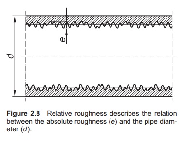
The friction coefficient depends on the pipe surface; this
is normally called the roughness of the pipe. Relative roughness (r) is defined as the rela-tion between
the absolute roughness (e) and the
diameter (d) of the pipe, r=e/d (Fig. 2.8). High
relative roughness gives high friction. The amount of
friction depends on the pipe material, the con-nection method and the age of
the pipe. For example, a new plastic pipe will have a lower fric-tion
coefficient than an old pipe. The fouling that occurs in pipes that have been
in use for some time will increase the roughness of the pipe. The f value for the pipe is given by the
manufacturer and for PE or PVC pipes normally ranges from 0.025 to 0.035. For
new pipes the value is lower, but when doing calculations values for old pipes
must be used.
The friction coefficient also depends on flow type. The
flow pattern can be divided into laminar and turbulent. The frictional losses
are much higher with turbulent flow. This will always be the case in pipes used
in aquaculture, because the water velocity is so high. Laminar flow may occur
in open channels with low water velocity. The Reynolds number
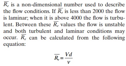
V =average water velocity
d =internal pipe diameter
v = kinematic viscosity.
Kinematic viscosity is the absolute viscosity divided by
the density of the liquid; the unit is m2/s (for-merlythe
stoke was used: 1 St = 16−4 m2/s). The kine-matic
viscosity tells us something about how easily the liquid flows: for instance,
oil will flow out slowly when drops are allowed to fall onto a horizontal
plate, while water will be distributed much faster. The kinematic viscosity of water
decreases with temperature; for example, is it reduced from 1.79 × 10⁻⁶ m2/s at 0°C to 1.00 × 10⁻⁶ m2/s at 20°C.11Salin-ity will also
increase the kinematic viscosity of water: with a salinity of 3.5% it is 1.83 m2/s at 0°C and 1.05
m2/s at 20°C.
Example
The average
velocity of fresh water in a pipe of internal diameter 123.8 mm is 1.5 m/s (0.1238 m).
The temperature is
20°C. Calculate the Reynolds number.
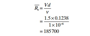
This clearly
illustrates that the water flow in the pipe is in the turbulent area.
By calculating the Reynolds number and the rela-tive
roughness of the pipe, the friction coefficient f, can be found from the Moody diagram (Fig. 2.9).
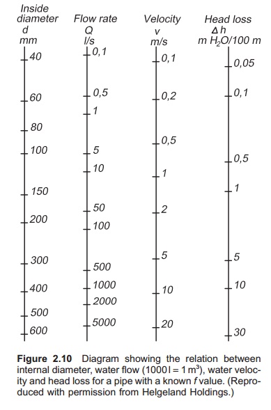
Computer programs and special diagrams (Fig. 2.10) are
available for calculating the head loss caused by friction inside a pipe. It is
important to be aware that these diagrams are specific for given pipes because
the f- value of the actual pipe is
used to construct them.
Example
Calculate the head
loss in an old PE pipe with inter-nal diameter of 110 mm (0.11 m). The length
of the pipe is 500 m and the velocity in the pipe is 1.5 m/s; the friction
coefficient is 0.030.
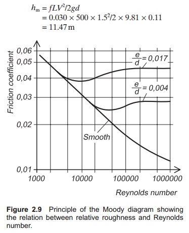
This means that the
head loss in the water flowing through the pipeline is 11.47 m. If the water is
to flow in the pipe, the intake pressure must be at least 11.47 mH2O in addition to atmospheric pressure; if it is less, the
flow rate through the pipe will be reduced.
Related Topics