Chapter: Aquaculture Engineering : Sea Cages
Calculation of the size of the mooring system
Calculation of the size of the mooring system
Mooring analysis
A calculation of the size of a mooring system must include a performance analysis under extreme conditions, for instance for an intact mooring system, with a break in one of the mooring lines and with an increase in the water level compared to normal due to a storm tide of 1 m for example (requirements in the Norwegian standard for cages). The analysis must show that the mooring system will withstand such situations without breakdown.
What is then happening when the environmental forces affect a pre-stressed moored sea cage farm? A total environmental force (F) will try to move the cages out of their original position. In all mooring lines on the side where the forces F is acting there will be additional tension, and a corresponding reduction in the lines on the opposite side. Depending of the degree of pre-stress and the elasticity of the lines, there will be a drift away from the equilibrium position caused by the acting forces, but the farm will not drift freely. The mooring lines will gradually create an opposing force towards F that prevents the cage farm drifting freely. A new equilibrium position will be established where forces from the mooring lines are opposite and equal to the forces created by the environmental factors. The tension in the mooring lines on the side where the environmental forces are acting is now much higher than when the cages were in their original positions; there might also be slack in lines on the opposite side.
If, in addition, there are waves additional dynamic forces will be imposed on the farm and it will oscillate around the equilibrium position as long as the mooring system does not break. The maximum load in the mooring lines will therefore be higher than from the static current force.
If there is a break in one of the mooring lines due to unforeseen circumstances the farm will drift into a new equilibrium position. This movement will be determined by the tension in the broken line, the weight of the farm and the resistance against movement from the net bag and cage collars. When the farm is drifting and needs to be stopped, it is important that the tension in the remaining lines does not exceed their breaking strength. If this happens other lines will break and most probably this will result in progressive breaking of all the remaining mooring lines so the cages will drift freely. If one mooring line to a cage breaks, there is also the possibility that the cage will crash into another cage or fixed construction such as the walkway whilst drifting towards its new equilibrium position. This may cause a material break in the cage collar, for instance. When doing mooring calculations a break in one of the mooring lines will normally be tolerated, but progressive breaking must not occur in such situations.
Calculation of sizes for mooring lines
There will always be some inaccuracy when describing and calculating the environmental loads affecting cage farms. For example, this can be that the current velocity or wave height varies and might be slightly higher than expected. A load factor is recommended to compensate for the possible inac-curacy. Normally the load factors are between 1 and 1.5 depending on the uncertainty in the calculations of environmental loads. A load factor of 1.5 means that the environmental loads can be up to 50% more than those calculated and the mooring will still hold. The total force that is used in further calculations is then:
Ft=γiFE
where:
Ft=total force
FE=calculated environmental forces
γi=load factor.
In the new Norwegian standard for mooring analysis, the standard load factor is set at 1.15 for unmanned farms and 1.3 for continuously manned farms when doing static analysis i.e. the safety factor is larger.
The breaking strength of the different types of mooring line is also given with some accuracy by the suppliers and is based on a number of measurements. To take care of possible inaccuracy when testing the material, and minor variations in the materials, it is recommended that a material factor (gm) be used. However, will this vary with the material and the degree of testing of the material that has been performed. Normally it lies between 1.1 and 5. To find size of the mooring lines necessary this must be taken into consideration, which gives the following equation:
FR= FTγm
where:
FR=mooring forces (the force that the mooring lines shall tolerate)
FT=calculated total forces including load factor
γm = material factor.
The following material factors are used in the Norwegian standard for cage farms:14 chain, 1.5; synthetic rope with knot, 5.0; synthetic rope, 3.0; synthetic rope specially resistant to ageing, wave and water absorption 1.5.
Example
To show how a mooring analysis can be performed an example is shown where the mooring line, buoy and anchor are to be dimensioned (Fig. 15.24). On a cage farm the calculated environmental force that an anchoring line must take up is 1 t or approximately 10 kN. The length and type of mooring line, buoy type and size, and anchor type and size should be found to keep the farm in position. The depth of the site is 30 m and the bottom is sand. Current veloc-ity is set to 0.2 m/s.
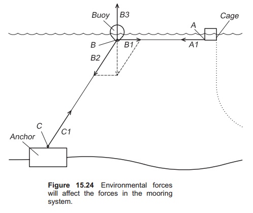
First the design of the mooring system must be found. Choose to have the buoys 15 m away from the cage collar. The mooring line is set to 3× the depth, and becomes 90 m. The total length of the mooring line is therefore 90 + 15 = 105 m. The forces on the buoys can then be found. First the angle a that the mooring line has from the bottom and to the surface must be found:
sinα= 30/ 90
a = 19.47°
Then calculate the force in the direction x on the mooring line:
cosα=10/x
x= 10/ cosα
x =10.61 KN
The mooring line must therefore tolerate a force of 10.61 kN.
Calculate the force in the y direction:
sinα=y/x
y= sin α x = 3.54 kN
The buoy will be dragged down with a force of 3.54 kN.
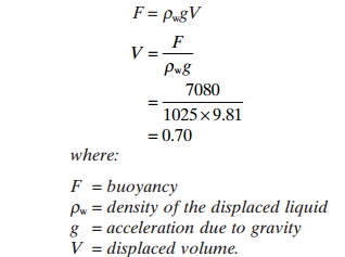
Now the buoy can be described. The requirement for buoyancy is set to twice the force F in the mooring line which is 7.08 kN. Archimedes law is used to calculate the buoyancy; the density of sea-water, rw= 1025 kg/m3.
This means that the buoy needs a volume of 700 l or more to stay in the correct position on the surface. In addition the buoy must have buoyancy that covers its own weight; this depends on buoy type and is given by the supplier.
The next step is to calculate the size of the anchor. A block anchor is chosen. First the size to withstand the vertical lifting force (y) is calculated:
y =3.54 kN
Choose a concrete block anchor with density fc of 2500 kg/m3. The weight of the anchor (G) is given by:
G = mg = ρcVg
where:
m = mass of anchor
V = volume of anchor
g = acceleration due to gravity
ρc = density of cancrete.
The buoyancy (F0) that will lift the anchor is, from Archimedes law:
F0=ρwVg
where:
ρw =density of seawater.
The following equation may be used to find the nec-essary volume of the block anchor (y):
y = G −Fo
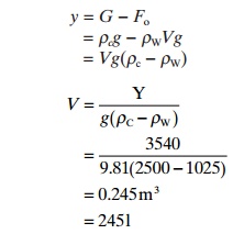
= 0.245m3
= 245 l
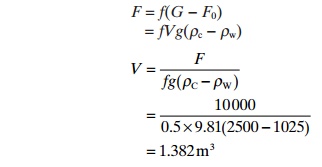
The horizontal force is calculated using a friction coefficient of 0.5 for the sand bottom. The horizontal force (F) that will try to move the anchor is 10 kN, while the weight G will keep the anchor in place. In addition the buoyancy F0 of the anchor will have effect, because it will reduce the weight com-pared to when it is on shore. The following equation can be set up:
where:
f = friction coefficient for the block anchor.
Therefore the volume of the block anchor must exceed 1.382 m3 or the mass be above 3.46 t. In practice two or three anchors will be used.
Related Topics