Chapter: Digital Logic Circuits : Asynchronous Sequential Circuits and Programmable Logic Devices
Analysis Procedure of Asynchronous Sequential Circuits
ASYNCHRONOUS SEQUENTIAL CIRCUITS
Asynchronous sequential circuits:
· Do not use pulses. The change of internal state occurs when there is a change in the input variable.
· Their memory elements are either unclocked flip flops or time delay elements.
· They often resemble combinational circuit with feedback.
· Their synthesis is much difficult than the synthesis of clocked synchronous sequential circuit.
· They are used when speed of operation is important.
The communication of two units, with each unit having its own independent clock, must be done with asynchronous circuits.
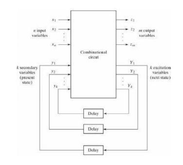
There are n input variables, m output variables, and k internal states.
The present state variables (y1 and y2) are called secondary variables. The next state variables (y1 and y2) are called excitation variables.
Fundamental mode operation assumes that the input signals change one at a time and only when the circuit is in a condition.
1. ANALYSIS PROCEDURE
The analysis of asynchronous sequential circuits proceeds in much the same way as that of clocked synchronous sequential circuits. From a logic diagram. Boolean expressions are written and then transferred into tabular form.
1. TRANSITION TABLE
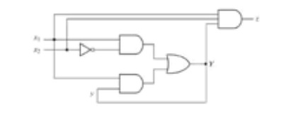
An example of an asynchronous sequential circuit is shown below:
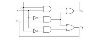
The analysis of the circuit starts by considering the excitation variables (y1 and y2).
As outputs and the secondary variables (y1 and y2) as inputs.
The Boolean expressions are:
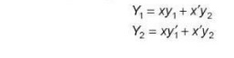
The next step is to plot the Y1 and Y2 functions in a map:
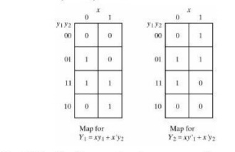
Combining the binary values in corresponding squares the following transition table is obtained.
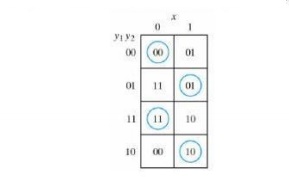
The transition table shows the values of Y=Y1Y2 inside each square. Those where Y=y are circled to indicate a stable condition.
The circuits has four stable total states –y1y2x= 000, 011, 110, and 100 and four unstable total states 001, 010, 111, and 100.
The state table of the circuit shown below:
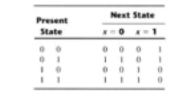
The table provides the same information as the transition table.
2. FLOW TABLE
In a flow states are named by letter symbols. Examples of flow tables are as follows.
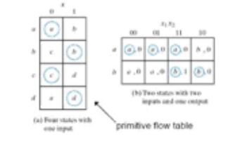
In order to obtain the circuit described by a flow table, it is necessary to assign to each state distinct value.
This assignment converts the flow table into a transition table. This is shown below:
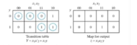
The resulting logic diagram is shown below:
3. RACE CONDITIONS
A race condition exists in an asynchronous circuit when two or more binary state variables change value in response to a change in an input variable, when unequal delays are encountered a race condition may cause the state variable to change in an unpredictable manner.
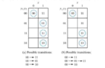
If the final stable state that the circuit reaches does not depend on the order in which the state variable change, the races are illustrated in the transition tables below:
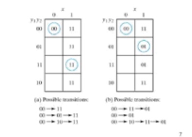
The transition tables below illustrate critical races:
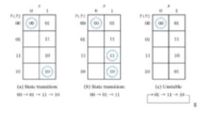
Races can be avoided by directing the circuit through a unique sequence of intermediate unstable states when a circuit does that, it is said to have a cycle. Examples of cycles are:
STATE ASSIGNMENTS
If one is able to reduce the total number of states, one may be able to save on the number of flip flops required for a design. This is the optimal situation. For example if a finite state machine drops from 7 states to 4 states and compact state assignment are used, the design drops from three flip flops to two flip flop. A sub optimal situation is when the number of states is reduced, but the number of flip flops is not. This does add don’t cares to the combinational logic that generates the next state equations. This will most likely drop the over all cost of the finite state machine.
Once the number states is at a minimum, then a judicious assignment of states may further reduce the cost of the next state equation and or the cost of the output equations. A set of heuristic rules is proposed where each rule is directed toward the reduction of the combinational logic in the finite state machine design.
As opposed to compact state assignments, one may propose a one hot state assignment. One hot is a set of state assignment in which a unique bit is one in the assignment for each state. This often lends to a reduction in the logic cost for the outputs, because in one and only one state a given output is asserted.
All of these topics will be discussed in more detail below.
Related Topics