Chapter: Digital Logic Circuits : Asynchronous Sequential Circuits and Programmable Logic Devices
Equivalent States and Reduction of State Table
EQUIVALENT
STATES AND REDUCTION OF STATE TABLE
The concept of equivalent states is
important for the design and testing of sequential networks. Two states in a
sequential network are said to be equivalent if we cannot tell them apart by
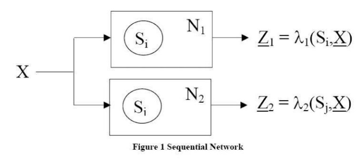
observing input and output sequences. Consider two sequential networks, N1
and N2 . N1 and N2
could be copies of the same network. N1 is started in state Si
and N2 is started in state Sj.
We apply the same input sequence X to both networks and observe the output
sequence Z1 and Z2 (the underscore notation indicates a
sequence) If Z1 and Z2 are the same , we reset the
networks to states Si and Sj apply a different input
sequence, and observe Z1 and Z2. If the output sequences
are the same for all possible input sequences, we say that Si and Sj
are equivalent (Si=Sj). Formally, we can define equivalent states as follows: Si=Sj if and only if,
for every input sequence X the output sequences Z1=ƛ1 (SiX)
and Z1=ƛ2 (sjX) are the same. This is not a
very practical way to test for state equivalent since, at least in theory, it
requires input sequences of infinite length, In we have a bound on number of
states, then we can limit the length of the test sequences.
A more practical way to determine state
equivalence uses the state equivalent theorem:
Si=Sj if and only of every single
input X, the outputs are the same and the next states are equivalent. When
using the definition of equivalence, we must consider all input sequences, but
we do not need any information about the internal state of the system. When
using the state equivalent theorem, we must look at both the output and next
states, but we need to consider only single inputs rather than input sequences.
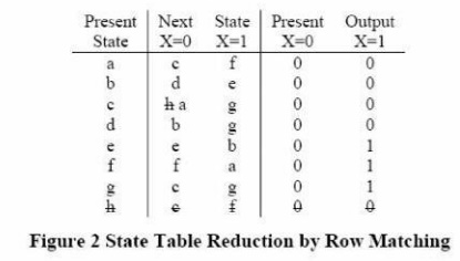
The table can be reduced by
eliminating equivalent states. First, observe that states a and h have the same
next states and outputs when X=0 and also when X=1. Therefore a=h so we can
eliminate row h and replace h with a in the table. To determine if any of the
remaining states are equivalent, we will use the state equivalent theorem. From
the table, since the outputs for states a and b are the same, a and b if and
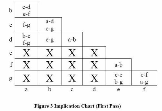
only if c=d and e=f. We say that c-d and e-f are implied pairs for a-b. To keep
track of the implied pairs, we make an implication chart, as shown. We place
c-d and e-f in the square at the intersection of row a and column b to indicate
the implication. Since states d and e have different outputs, we place an x in
the d-e square to indicate that d!=e. After completing the implication chart in
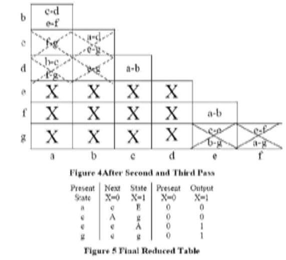
this way, we make another pass through the chart. The e-g so we X out the
square. Similarly, since, we x out the f-g square. On the next pass through the
chart, we X out all the squares that contain e-f or f-g as implied pairs (shown
on the chart with dashed xs). In the next pass no additional square are
X-ed out, so the process terminates.
Since all the squares corresponding to non equivalent states have been x=ed
out, the coordinates of the remaining squares indicate equivalent state pairs.
From the first column a= b from third column, c=d: and from the fifth column,
e=f.
The implication table method of
determining state equivalent can be follows:
1. Construct a chart contains a
square for each pairs of states.
2. Compare each pair of rows in the state
table. If the output associated with states I and j different, place an X in
square i-j to indicate that i!=j. If the outputs are the same, place the
implied pairs in square i-j (if the next states of I and j are m and n for some
input x, then m-n is implied pair). If the outputs and next states are the same
(or if i-j implies only itself), place a check (v) in square i-j to indicate
that i=j
3. Go through the table square by
square. If square i-j contains the implied pair m-n and square m-n contains an
x, then i!=j, and an X should be placed in square i-j.
4. If any Xs were added in step3
until no more Xs are added.
5. For each square i-j that does not
contain an X, i=j.
If desired, row matching can be used
to partially reduce the state table before constructing the implication table.
Although we have illustrated for a mealy
table, the same procedure applies to a more table.
Two sequential networks are said to
be equivalent if very state in the first network has an equivalent state in the
second network, and vice versa.
EQUIVALENT
STATES: Two
states in a sequential network are said to be equivalent if we cannot tell them
apart by observing input and output sequences.
SUCCESSIVE
PARTITIONING:
A method for fining equivalent states by partitioning states based on outputs
and next states.
IMPLICATION
CHART: A tabular
method for finding equivalent states based upon outputs implication made by
next states.
REDUCED
STATE TABLE:
A state table in which all but one the equivalent states has been removed.
The next step is to make a
assignment that relates the flip flops states to the states in the table. The
best state assignment to use depends on a number of factors. In many cases, we
should try to find an assignment that will reduce the amount of required logic.
For some types of programmable logic, a straight binary state assignment will work
just as well as any other. For programmable gate arrays, a one hot assignment
may be perfected.
In order to reduce amount of logic
required, we will make a state assignment using the following guidelines.
1. States
that have the same next state (NS) for a given input should be given adjacent
assignment (look at the columns of the state table)
2. States
that are the next states of the same state should be given adjacent assignment
(look at the rows)
3. States
that have the same output for a given input be given adjacent assignments.
Using these guidelines tends to
chump is together on the karnaugh maps for the next state and output functions
. The guidelines indicates that the following states should be given adjacent
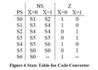
assignment for the state table of Figure 6.
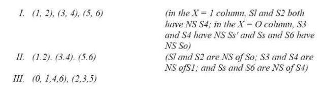
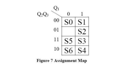
Figure 7 gives an assignment map,
which satisfies the guidelines, and the corresponding transition table. Since
state 001 is not used, the next state and outputs for this state are don’t cares.
Related Topics