Chapter: Electrical and electronics : Circuit Theory
Problem on Parallel Networks
PARALLEL NETWORKS:
Problem 1: Figure shows three resistors, R1, R2 and R3 connected across each other, i.e. in parallel, across a battery source
of V volts.
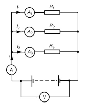
In a parallel circuit:
(a) the sum of the currents I1, I2 and I3 is equal to the total circuit current, I, i.e. I =I1 +I2 +I3, and
the source p.d., V volts, is the same across each of the
From OhmŌĆÖs law:
I1 = V/R1
, I2 = V/R2
, I3 = V/R3 and I = V/R
where R is the total circuit resistance. Since I =I1 + I2 + I3
then
V/R= V/R1+ V/R2+ V/R3 Dividing throughout by V gives:
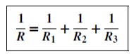
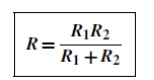
This equation must be used when finding the total resistance R of a parallel circuit. For the special case of two resistors in parallel
Problem 2: For the circuit shown in Figure , determine (a) the reading on the ammeter, and (b) the value of resistor R2.
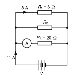
P.d. across R1 is the same as the supply voltage V.
Hence supply voltage, V =8 ├Ś 5=40V
(a) Reading on ammeter, I = V R3= 40/20=2A
Current flowing through R2 =11ŌłÆ8ŌłÆ2=1A
Hence, R2 = V/I2= 40/1=40 ╬®
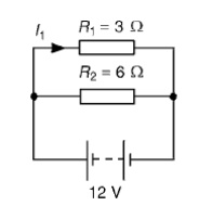
(a) The total circuit resistance R is given by 1/R= 1/R1+ 1/R2= 1/3+ 1/6
1/R= 2 + 1/6= 3/6 Hence, R = 6/3= 2 ╬®
(b) Current in the 3 ╬®resistance, I1 = V R1= 12/3= 4A
Problem 3: For the circuit shown in Figure find (a) the value of the supply voltage V and (b) the value of current I.
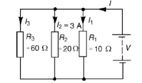
(a) P.d. across 20 ╬®resistor = I2R2 = 3├Ś 20 = 60V, hence supply voltage V =60V since the circuit is connected in parallel.
(b)Current I1 = V/R1= 60/10= 6A; I2 = 3A
I3 = V/R3= 60/60= 1A
Current I =I1+I2+I3 and hence I =6+3+1=10A Alternatively,
1/R= 1/60+ 1/20+ 1/10= 1 + 3 + 6/60= 10/60 Hence total resistance R= 6010=6 ╬® Current I = V/R= 60/6=10A
Problem 4: Find the equivalent resistance for the circuit shown in Figure
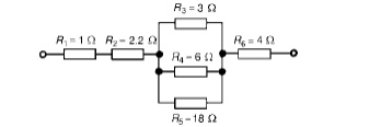
R3, R4 andR5 are connected in parallel and their equivalent resistance R is given by: 1/R= 1/3+ 1/6+ 1/18=6 + 3 + 1/18= 10/18
Hence R= 18/10=1.8 ╬®
The circuit is now equivalent to four resistors in series and the equivalent circuit resistance =1+2.2+1.8+4=9 ╬®
Related Topics