(LIC) - Important Questions and Answers: Linear Integrated Circuits : Applications of Operational Amplifier | Linear Integrated Circuits : Applications of Operational Amplifier
Chapter: Linear Integrated Circuits : Applications of Operational Amplifier
Important Questions and Answers: Linear Integrated Circuits : Applications of Operational Amplifier
APPLICATIONS OF OPERATIONAL
AMPLIFIERS
PART-A
1. Mention some of the linear
applications of op – amps.
Adder,
subtractor, voltage –to- current converter, current –to- voltage converters,
instrumentation amplifier, analog computation, power amplifier, etc are some of
the linear op amp circuits.
2. Mention some of the non – linear
applications of op-amps
Rectifier,
peak detector, clipper, clamper, sample and hold circuit, log amplifier,
anti–log amplifier, multiplier are some of the non – linear op-amp circuits.
3. What are the areas of application
of non-linear op- amp circuits?
1.
Industrial instrumentation
2.
Communication
3.
Signal processing
4. What is voltage follower?
A
circuit in which output follows the input is called voltage follower.
5. What is the need for an
instrumentation amplifier?
In
a number of industrial and consumer applications, the measurement of physical
quantities is usually done with the help of transducers. The output of
transducer has to be amplified So that it can drive the indicator or display
system. This function is performed by an instrumentation amplifier.
6. List the features of
instrumentation amplifier:
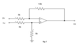
1.
High gain accuracy
2.
High CMRR
3.
High gain stability with low temperature co-efficient
4
Low dc offset
5.
Low output impedance
7. What are the applications of V-I
converter?
1.
Low voltage dc and ac voltmeter
2.
LED
3.
Zener diode tester
8. Define Band pass filter.
The
band pass filter is the combination of high and low pass filters, and this
allows a specified range of frequencies to pass through.
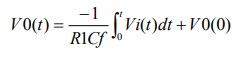
9. Write transfer function of op amp
as an integer.
The
transfer function of the integer is IAI=1/WR1cf
10. What do you mean by a precision
rectifier?
The
major limitation of ordinary diode is that it cannot rectify voltages below the
cut – in voltage of the diode. A circuit designed by placing a diode in the
feedback loop of an op – amp is called the precision diode and it is capable of
rectifying input signals of the order of millivolt.
11. Write down the applications of
precision diode.
1.
Half - wave rectifier
2.
Full - Wave rectifier
3.
Peak – value detector
4.
Clipper
5.
Clamper
12. Define Logarithmic and
antilogarithmic amplifier.
When
a logarithmic PN junction is used in the feedback network of op-amp, the
circuit exhibits log or antilog response. The logarithmic amplifier is a
current to voltage converter with the transfer characteristics v0=vi In(If/Ii)
Antilog amplifier is a decoding circuit which converts the logarithmically
encoded signal back to the original signal levels as given by vl=vR10-kvi
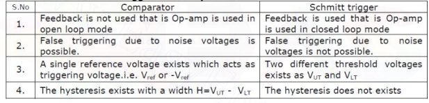
13. Differentiate Schmitt trigger
and comparator.
Comparator.
1.It
compares the input signal with references voltage then yields the output
voltage . comparator output need not to be square wave
2.
It need not consist of feedback
Schmitt
trigger
1.
It operates between two reference points namely UTP<P.
2.
It employs positive feedback
3.
Its output is square wave.
14. List the applications of Log
amplifiers:
1.
Analog computation may require functions such as lnx, log x, sin hx etc. These
functions can be performed by log amplifiers
2.
Log amplifier can perform direct dB display on digital voltmeter and spectrum
analyzer
3.
Log amplifier can be used to compress the dynamic range of a signal
4.
Comparator output need not to be square wave
15. Write down the condition for
good differentiation.
1.For
good differentiation, the time period of the input signal must be greater than
or equal to Rf C1
2.
T> =R f C1 Where, R f is the feedback resistance
3.
C f is the input capacitance
16. What is a comparator?
A
comparator is a circuit which compares a signal voltage applied at one input of
an op amp with a known reference voltage at the other input. It is an open loop
op - amp with output +Vsat.
17. What are the applications of
comparator?
1.
Zero crossing detectors
2.
Window detector
3.
Time marker generator
4.
Phase detector
18. What is a Schmitt trigger?
Schmitt
trigger is a regenerative comparator. It converts sinusoidal input into a
square wave output. The output of Schmitt trigger swings between upper and
lower threshold voltages, which are the reference voltages of the input
waveform.
19. What is a Schmitt trigger?
Schmitt
trigger is a regenerative comparator. It converts sinusoidal input into a
square wave output. The output of Schmitt trigger swings between upper and
lower threshold voltages,
20. Which are the reference voltages
of the input waveform?
i.
RC phase shift oscillator
ii.
Wein bridge oscillator
21. What are the characteristics of
a comparator?
1.
Speed of operation
2.
Accuracy
3.
Compatibility of the output
22. What is a filter?
Filter
is a frequency selective circuit that passes signal of specified band of
frequencies and attenuates the signals of frequencies outside the band
23. What are the demerits of passive
filters?
Passive
filters works well for high frequencies. But at audio frequencies, the
inductors become problematic, as they become large, heavy and expensive. For
low frequency applications, more number of turns of wire must be used which in
turn adds to the series resistance degrading inductor’s performance ie, low Q,
resulting in high power dissipation.
24. What are the advantages of
active filters?
Active
filters used op- amp as the active element and resistors and capacitors as
passive elements.
25. Give the schematic of op-amp
based current to voltage converter.
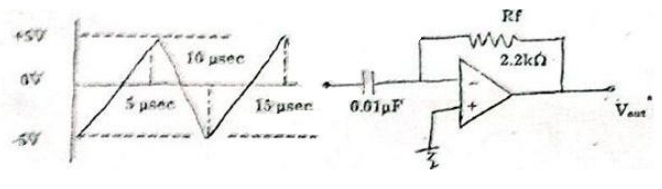
26. Draw the circuit diagram of
differentiator and give its output equation
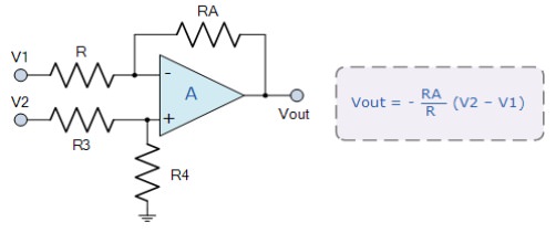
27. Compare the performance of
inverting and non-inverting operational amplifier configurations.
Inverting
Amplifier:
Gain
= -Rf / Ri
Input
resistance = Ri
Non
Inverting Amplifier:
Gain
= 1+Rf / Ri Input resistance = Very large (∞)
28. Why is frequency compensation
required in operational amplifier?
To
improve Stability of the circuit.
29. How do the precision rectifiers
differ from the conventional rectifier
To
rectify voltage below the cut in voltage (0.7V) of a diode.
30. What are the important features
of an instrumentation amplifier
High
gain accuracy, High CMRR, Low DC offset & low output impedance.
31. What is comparator?
It
is a circuit which compares a signal voltage applied at one input of an op-amp
with a known reference at other input.
32. Give an application of an
Inverting Amplifier.
Scale
changer, inverting summer.
33. Draw and write equation of an
integrator using an op-amp.
34. Give one application of voltage
follower, Schmitt Trigger, Clamper and Peak Detector.
Schmitt
Trigger – Squarer circuit
Clamper
– Analog TV receivers
Peak
Detector – AM communication
35. Define Bandwidth of a filter?
Bandwidth
is the difference between the upper and lower cutoff frequencies.
36. What is Hysteresis and mention
the purpose of hysteresis in a comparator.
The
difference between upper and lower threshold voltages in a comparator is called
hysteresis. The voltage span of hysteresis is set to be greater than the peak
to peak noise voltage. Therefore there will not be any incorrect variations due
to noise signals.
37. Determine the output voltage for
the circuit shown in figure 1 when
a.Vin=-2V
and
b.Vin=3V
Given
V cc=+-10V e+=1.5 e - =Vin
38. Design and sketch an operational
amplifier subtractor circuit.
39. What is the difference between
basic comparator and Schmitt trigger?
In
electronics, a Schmitt trigger is a comparator circuit with hysteresis
implemented by applying positive feedback to the noninverting input of a
comparator or differential amplifier. ... In the non-inverting configuration,
when the input is higher than a chosen threshold, the output is high.
40. Draw the circuit diagram of a
comparator. Mention its applications.
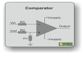
Applications
of Comparator:
Threshold
Detector, Zero Crossing Detector and Schmitt Trigger
41. Mention some of the linear
applications of op – amps.
Adder,
subtractor, voltage –to- current converter, current –to- voltage converters,
instrumentation amplifier, analog computation ,power amplifier, etc are some of
the lin ar op-amp circuits.
42. Mention some of the non – linear
applications of op-amps.
Rectifier,
peak detector, clipper, clamper, sample and hold circuit, log amplifier, anti
–log amplifier, multiplier are some of the non – linear op-amp circuits.
43. Define virtual ground property
of Op-amp.
Concept
of virtual ground says that the two input terminals of the Op-amp are always at
the same potential. Thus if one terminal is grounded the other can be assumed
to be at ground potential, which is called virtual ground.
44. What is Voltage follower?
•
A circuit in which the output voltage follows th input voltage is called
voltage follower Circuit.
•
In Op-amp if the inverting input and the output terminals are shorted and if
any signal is Applied at the non-inverting terminal, it appears at the output
without any change.
•
It is also called as source follower, unity gain amplifier, buffer amplifier or
isolation amplifier.
45. Calculate the output voltage V0
of the circuit shown in fig. 1
46. Draw the circuit diagram of
voltage follower using IC 741.
47. For the op-amp shown, determine
the voltage gain.
48. List the features of
instrumentation amplifier.
·
High
gain accuracy
·
High
CMRR
·
High
gain stability with low temperature co-efficient
·
Low
dc offset
·
Low
output impedance
49. What are the applications of V-I
converter?
·
Low
voltage dc and ac voltmeter
·
LED
·
Zener
diode tester
50. What do you mean by a precision
diode?
The
major limitation of ordinary diode is that it cannot rectify voltages below the
cut – in voltage of the diode. A circuit designed by placing a diode in the
feedback loop of an op – amp is called the precision diode and it is capable of
rectifying input signals of the order of milli volt.
51.What are the limitations of the
basic differentiator circuit?
At
high frequency, a differentiator may become unstable and break into
oscillations. The input impedance decreases with increase in frequency ,
thereby making the circuit sensitive to high frequency noise.
52. Write down the condition for
good differentiation.
For
good differentiation, the time period of the input signal must be greater than
or equal to RfC1
T
> RfC1 Where, Rf is the feedback resistance Cf
is the input capacitance
53. What are the applications of
comparator?
·
Zero
crossing detector
·
Window
detector
·
Time
marker generator
·
Phase
detector
54. What is a Schmitt trigger?
Schmitt
trigger is a regenerative comparator. It converts sinusoidal input into a
square wave output. The output of Schmitt trigger swings between upper and
lower threshold voltages, which are the reference voltages of the input
waveform.
55. Differentiate Schmtt trigger and
comparator
56. Define logarithmic and
antilogarithmic amplifier.
The
Op-amp circuit in which the output is proportional to the logarithmic of the
input is called logarithmic amplifier. It employs a diode or a transistor in
the gative feedback path.
The
Op-amp circuit in which the output is proportional to the antiloga ithmic of
the input is called logarithmic amplifier. It employs a diode or a transistor
in the input stage.
57. List the applications of Log
amplifiers.
·
Analog
computation may require functions such as ln x, log x, sin h x etc.
·
These
functions can be performed by log amplifiers
·
Log
amplifier can perform direct dB display on digital voltmeter and spectrum
analyzer
·
Log
amplifier can be used to compress the dynamic range of a signal
58. What is a filter?
Filter
is a frequency selective circuit that passes signal of specified band of
frequencies and attenuates the signals of frequencies outside the band.
59. What are the advantages of
active filters?
·
Active
filters used op- amp as the active element and resistors and capacitors as
passive elements.
·
By
enclosing a capacitor in the feedback loop , inductor less active filters can
be obtained
·
Op-amp
used in non – inverting configuration offers high input impedance and low
output impedance, thus improving the load drive capacity.
60.What are the requirements for
producing sustained oscillations in feedback circuits?
For
sustained oscillations,
·
The
total phase shift around the loop must be zero at the desired frequency of
oscillation, fo. ie, AB =0 (or) 360°
·
At
fo, the magnitude of the loop gain | A β | should be equal to unity
PART-B
1.
Design a fourth order Butterworth LPF having a upper cutoff frequency of 1KHz.
2.
Design a square wave oscillator for f0 = 1 KHz using 741 op-amp and a DC
supply voltage of +/-12V.
3.
a) Discuss the working of instrumentation amplifier . Name two applications of
the same.
4.
Discuss in detail the working of a RC phase shift oscillator.
5.
Design Wien Bridge oscillator of 1 KHz frequency.
6.
Design an op – amp Schmitt trigger with VUT= 2V, VLT= -4V & the output
swings b/w +10V. If the i /p is 5 sin wt, plot i/p & o/p waveforms.
7.
a) Compare the RC phase shift and Wien bridge oscillator.
b)
Design a RC phase shift oscillator and a Wien bridge oscillator of frequency 1
KHz. (Assume C= 0.01 μF).
8.
With diagram explain the operation of inverting and non-inverting amplifier.
9.
Draw the circuit diagram of a second order Butterworth active LPF and derive
its transfer function.
10.
Draw an instrumentation amplifier whose gain is controlled by adjustable gain
and explain its Working concept.
11.
Explain the circuit operation of logarithmic amplifier with two op-amps.
12.
With neat circuit, explain the operation of Schmitt trigger.
13.
Explain about positive and negative clipper.
14.
Explain about zero crossing detector and peak detector.
15.
With the help of circuits and necessary equations, explain how log and antilog
computations are performed using IC741.
16.
Explain the operation of the following op-amp applications.
a.
Scale Changer
b.
Voltage follower
c.
Non-Inverting adder
d.
Integrator
17.
(i) Design a first order Low-pass filter for cut-off frequency of 2 KHz and
pass-band gain of 2.
(ii)
Explain a positive clipper circuit using an Op-amp and a diode with neat
diagrams .
18.
(i) Design a circuit to implement V0=0.545V3+ 0.273V4−1.25 V1−2V2.
(ii)
Draw and explain a simple Op-amp differentiator. Mention its limitations.
Explain with a neat diagram how it can be overcome in a practical
differentiator. Design an Op-amp differentiator that will differentiate an
input signal with maximum frequency f max =100Hz.
19.
With relevant circuits, explain the following applications of OPAMP.
(i)
Voltage to current converters
(ii)
Multiplier
20.
(i) Explain the steps involved in the design of a band pass filter using OPAMP.
(ii) Write a note on Schmitt trigger.
21
(i).Sketch the basic circuit using op amp to perform the mathematical operation
of differentiation and explain? What are the limitations of an ordinary op-amp
differentiator? Draw and explain the operation of a practical differentiator
that will eliminate the limitations.
(ii)
Draw and explain the circuit of a voltage to current convertor if the load is
(1)
Floating (2) Grounded
22.
(i) Explain the working of OP-AMP based Schmitt trigger circuit.
(ii)Design
OP-AMP based second order active low pass filter with cut off frequency 2 kHz.
23.
a) i) What do you understand by an Instrumentation Amplifier?
ii)
State the requirements of a good Instrumentation Amplifier.
iii)
Draw the circuit diagram and explain the working of Instrumentation Amplifier.
iv)
Mention the specific advantages of three op-amp Instrumentation Amplifier
circuit.
24.
i) What do you understand by an Integrator?
ii)
Draw and explain an ideal active op-amp Integrator circuit.
iii)
Draw the I/O waveforms for integrator
1)
Step input signal.
2)
Square wave input signal
3)
Sine wave input signal.
Derive
the expression for change in output voltage.
iv)
List the applications of practical Integrator.
v)
Design a practical integrator circuit with a dc gain of 10, to integrate a
square wave of 10 KHz.
25.
Explain the working of i) Instrumentation Amplifier ii) Schmitt Trigger ,
,
26.
Explain the working of i) Precision Full wave rectifier ii) Integrator ,
27.
With the neat diagram explain logarithmic amplifier and Antilogarithmic
Amplifier
28.
With neat diagram explain the application of op amp as precision rectifier,
Clipper, and Clamper.
29. Explain in detail about V –I and I-V
convertor.
30.
Design a wide band pass filter with fL= 400Hz, fH= 2 kHz and a pass band gain
of4.Find the value Q of the filter.
31.
Determine the rate of change of the output voltage in response to the first
input pulse as shown below for the integrator. The output voltage is initially
zero. Also describe the output after the first pulse. Draw the output waveform.
32.
Explain in detail about the V to I and I to V converters.
33.
With a neat circuit diagram, explain the working of the precision rectifier.
34.
Explain the application of operational amplifier as differentiator.
35.
Mention two advantages of active filter over passive filter. Also design a
second order low pass filter using operational amplifier for the upper cut off
frequency of 2 kHz. Assume the value of capacitor to be 0.1μF.
36.
With a neat circuit diagram explain the working of voltage to current
converter.
37.
Explain the working of an op-amp differentiator and derive its output equation.
38.
What is the need for V to I and I to V converter? How are they realized using
op-amp?
39.
What is the purpose of a precision rectifier? How are they realized using
op-amp? Explain
40.
Draw the regenerator comparison circuit and obtain expression for UTP and LTP
41.
Draw the circuit diagram of an instrumentation amplifier and explain its
operation. List few applications.
42. How an op-amp can be used as an Log
amplifier
43.
Design a second order high pass Butterworth filter having cut off frequency of
5Khz.
44.
What is a precision rectifier? With circuit schematic explain the working
principle of full wave rectifier.
45.
Using IC741,design a capacitor coupled non inverting amplifier circuit to
operate with a 24v supply. The voltage gain is 100,output amplitude is 6V and
lower cut –off frequency is to be 100 Hz to drive a minimum load resistance of
5.6kΩ.
46.
For the instrumentation amplifier using two ideal opamp shown in Fig.1 verify
the equation
Vo
= (1 + R2/R1 + 2R2/R3 ) (V2-V1)
47.
Prove that the voltage gain and input resistance with feedback of an inverting
amplifier is given by Avf = ( - Arf) / (R1(1+A)+ Rf) and
Rif = (R1+ Rf/(1+A)) ║Ri
48.
Design an adder circuit using an opamp to get the output expression as Vo= -
(0.1 V1+V2+10V3).
49.
Design an opamp differentiator that will differentiate an input signal with
Fmax=100 Hz.
Draw
the output waveform for a sinewave of 1V peak at 100 Hz applied to the
differentiator.
50.
Consider the lossy integrator.For component values R1=10K, Rf= 100K, Cf=10nF,
Determine the lower limit of integration.
51.
Design a second order butterworth Low pass filter having upper cut off
frequency 1 KHz.
52.
Find the output voltage vo of the given circuit when input Vi=10mV,Vi=100 mv
and Vi=1V.
53.
Design a circuit to implement Vo =0.545V3+0.273V4- 1.25 V1- 2V2.
54.
Calculate Vo of the output current in given circuit if E1 equals i)+5V ii) –
2V. For each situation, state if the opamp sources or sinks.
Related Topics