Applications of Operational Amplifier - Voltage to Current Converter with floating loads (V/I) | Linear Integrated Circuits : Applications of Operational Amplifier
Chapter: Linear Integrated Circuits : Applications of Operational Amplifier
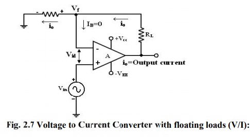
Voltage to Current Converter with floating loads (V/I)
Voltage to
Current Converter with floating loads (V/I):
Voltage
to current converter in which load resistor RL is floating (not
connected to ground). Vin is applied to the non- inverting input
terminal, and the feedback voltage across R1 devices the inverting
input terminal. This circuit is also called as a current – series negative
feedback amplifier. Because the feedback voltage across R1 (applied
Non-inverting terminal) depends on the output current i0 and is in
series with the input difference voltage Vid.
Writing
KVL for the input loop,
Voltage
Vid=Vf and IB
= 0 , vi=RLi0 = where = i0=vi/RL
From
the fig input voltage Vin is converted into output current of Vin/RL
[Vin -> i0]. In other words, input volt appears across
R1. If RL is a precision resistor, the output current
(i0
= Vin/R1) will be precisely fixed
Applications:
1.
Low
voltage ac and dc voltmeters
2.
Diode
match finders
3.
LED
and Zener diode testers.
Voltage – to current converter with Grounded load:
This
is the other type V – I converter, in which one terminal of the load is
connected to ground.
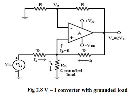
Analysis of the circuit:
The
analysis of the circuit can be done by following 2 steps.
1.
To determine the voltage V1 at the non-inverting (+) terminals and
2.
To establish relationship between V1 and the load current IL.
Applying KCL at node a,
R=
Rf
I1
+I2=IL
(Vi +Va)/R + (V0
–Va )/R= IL
Vo
= (Vi +Vo - IL R)/2 and gain =1+ R/R= 2.
∴Vi =ILR ; IL=Vi/R
Current to Voltage Converter (I –V):
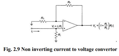
Open
– loop gain A of the op-amp is very large. Input impedance of the op amp is
very high.
Sensitivity of the I – V converter:
1.
The
output voltage V0 = -RF Iin.
2.
Hence
the gain of this converter is equal to -RF. The magnitude of the gain (i.e.) is
called as sensitivity of I to V converter.
3.
The
amount of change in output volt ∆V0 for a given change in the input current
∆Iin is decide by the sensitivity of I-V converter.
4.
By
keeping RF variable, it is possible to vary the sensitivity as per the
requirements.
Applications of V-I converter with Floating Load:
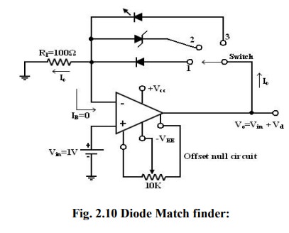
1. Diode Match finder:
In
some applications, it is necessary to have matched diodes with equal voltage
drops at a particular value of diode current. The circuit can be used in
finding matched diodes and is obtained from fig (V-I converter with floating
load) by replacing RL with a diode.
When
the switch is in position 1: (Diode Match Finder) Rectifier diode (IN 4001) is
placed in the f/b loop, the current through this loop is set by input voltage Vin
and Resistor R1. For Vin = 1V and R1 = 100Ω,
the current through this I0 = Vin/R1 = 1/100 = 10mA. As
long as V0 and R1 constant, I0 will be
constant. The Voltage drop across the diode can be found either by measuring
the volt across it or o/p voltage.
The
output voltage is equal to (Vin +VD) V0= Vin
+ VD.
To
avoid an error in output voltage the op-amp should be initially nulled. Thus
the matched diodes can be found by connecting diodes one after another in the
feedback path and measuring voltage across them.
2. Zener diode Tester:
(When
the switch position 2) when the switch is in position 2, the circuit becomes a
Zener diode tester. The circuit can be used to find the breakdown voltage of
Zener diodes. The Zener current is set at a constant value by Vin and R1. If
this current is larger than the knee current (IZK ) of the Zener,
the Zener blocks (Vz ) volts. For Ex: IZK = 1mA , VZ =
6.2V, Vin = 1V, R1 = 100Ω Since the current through the Zener is ,
I0 = Vin/R1 = 1/100 =10mA > IZK the voltage across the
Zener will be approximately equal to 6.2V.
3. When the switch is in position 3: (LED)
The
circuit becomes a LED when the switch is in position 3. LED current is set at a
constant value by Vin and R1. LEDs can be tested for
brightness one after another at this current.
Matched
LEDs with equal brightness at a specific value of current are useful as
indicates and display devices in digital applications.
Applications of I – V Converter:
One
of the most common uses of the current to voltage converter is
1.
Digital
to analog Converter (DAC)
2.
Sensing
current through Photo detector. Such as photo cell, photo diodes and
photovoltaic cells.
Photoconductive
devices produce a current that is proportional to an incident energy or light
(i.e).
It
can be used to detect the light.
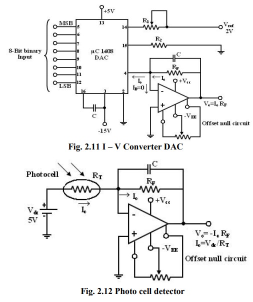
Photocells,
photodiodes, photovoltaic cells give an output current that depends on the
intensity of light and independent of the load. The current through these
devices can be converted to voltage by I – V converter and it can be used as a
measure of the amount of light. In this fig photocell is connected to the I – V
Converter. Photocell is a passive transducer it requires an external dc voltage
(Vdc). The dc voltage can be eliminated if a photovoltaic cell is
used instead of a photocell. The Photovoltaic Cell is a semiconductor device
that converts the radiant energy to electrical power. It is a self- generating
circuit because it does not require dc voltage externally. Ex of Photovoltaic
Cell: used in space applications and watches.
Related Topics