Applications of Operational Amplifier - Antilog Amplifier using Operational Amplifier | Linear Integrated Circuits : Applications of Operational Amplifier
Chapter: Linear Integrated Circuits : Applications of Operational Amplifier
Antilog Amplifier using Operational Amplifier
Antilog
Amplifier
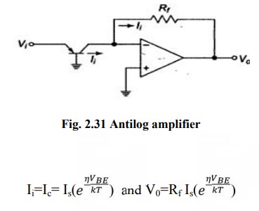
A
circuit to convert logarithmically encoded signal to real signals. Transistor
in inverting input converts input voltage into logarithmically varying currents.

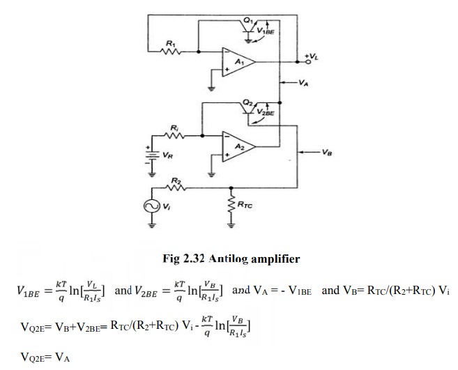
The
circuit is shown in figure below. The input Vi for the antilog-amp is fed into
the temperature compensating voltage divider R2 and RTC
and then to the base of Q2. The output of A2 is fed back to R1
at the inverting input of op amp A1. The non-inverting inputs are
grounded


The
output Vo of the antilog- amp is fed back to the inverting input of
A1 through the resistor R1.
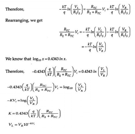
Hence
an increase of input by one volt causes the output to decrease by a decade.
Related Topics