Applications of Operational Amplifier - Active filters using Operational Amplifier | Linear Integrated Circuits : Applications of Operational Amplifier
Chapter: Linear Integrated Circuits : Applications of Operational Amplifier
Active filters using Operational Amplifier
Active
filters:
An
electric filter is often a frequency selective circuit that passes a specified
band of frequencies and blocks or alternates signal and frequencies outside
this band. Filters may be classified as
1.
Analog
or digital.
2.
Active
or passive
3.
Audio
(AF) or Radio Frequency (RF)
1. Analog
or digital filters:
Analog
filters are designed to process analog signals, while digital filters process
analog signals using digital technique.
2. Active or Passive:
Depending
on the type of elements used in their construction, filter may be classified as
passive or Active elements used in passive filters are Resistors, capacitors,
inductors. Elements used in active filters are transistor, or op-amp.
Active filters offer the following advantages over passive filters:
1.
Gain and Frequency adjustment flexibility:
Since
the op-amp is capable of providing gain, the i/p signal is not attenuated as it
is in a passive filter. [Active filter is easier to tune or adjust].
2.
No loading problem:
Because
of the high input resistance and low o/p resistance of the op-amp, the active
filter does not cause loading of the source or load.
3.
Cost:
Active
filters are more economical than passive filter. This is because of the variety
of cheaper op-amps and the absence of inductors.
The
most commonly used filters are these:
1.
Low
pass Filters
2.
High
pass Filters
3.
Band
pass filters
4.
Band
–reject filters
5.
All
pass filters.
Frequency response of the active filters:
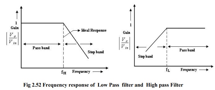
Low pass filters:
1. It has a constant gain from 0 Hz to
a high cutoff frequency f1.
2. At fH the gain in down by 3db.
3.
The frequency between 0 Hz and fH are known as the pass band frequencies where
as the range of frequencies those beyond fH, that are attenuated includes the
stop band frequencies.
4. Butterworth, Chebyshev and Cauer
filter are some of the most commonly used practical filters.
5. The key characteristics of the
butter worth filter are that it has a flat pass band as well as stop band. For
this reason, it is sometimes called flat- flat filters.
6. Chebyshev filter -> has a ripple
pass band & flat stop band.
7. Causer Filter -> has a ripple
pass band & ripple stop band. It gives best stop band response among the
three.
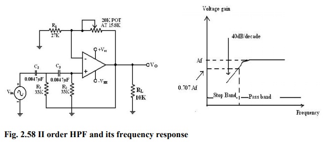
High pass filter:
High
pass filter with a stop band 0 <f< f L and a pass band f> f
L
fL
-> low cut off frequency
f
-> operating frequency.
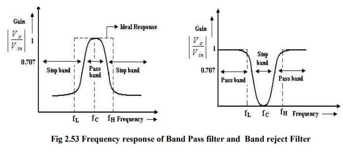
Band pass filter:
It
has a pass band between 2 cut off frequencies fH and fL
where fH > fL and two, stop bands: 0<f< fL
and f > fH between the band pass filter (equal to fH -
fL).
Band
–reject filter: (Band stop or Band elimination)
It
performs exactly opposite to the band pass.
It
has a band stop between 2 cut-off frequency fL and fH and 2 pass bands:
0<f< fL and f> fH fC -> center frequency.
Note:
The
actual response curves of the filters in the stop band either R or S
or both with Rin frequencies.
The
rate at which the gain of the filter changes in the stop band is determined by
the order of the filter.
Ex: 1st order low pass filter the gain
rolls off at the rate of 20dB/decade in the stop band.
(i.e)
for f > fH.
2nd
order LPF -> the gain roll off rate is 40dB/decade.
1st
order HPF -> the gain rolls off at the rate of 20dB (i.e.) until f:fL
2nd
order HPF -> the gain rolls off at the rate of 40dB/decade
First order LPF Butterworth filter:
First
order LPF that uses an RC for filtering op-amp is used in the non inverting
configuration. Resistor R1 & Rf determine the gain of the filter. According
to the voltage –divider rule, the voltage at the non-inverting terminal (across
capacitor) C is,
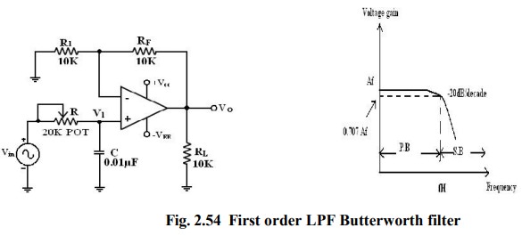
Gain
A= (1+Rf/R1)
Voltage
across capacitor V1= Vi
/ (1+j2πfRC)
Output
voltage V0 for non inverting amplifier =A V1
=
(1+Rf/R1) Vi/(1+j2πfRC)
Overall
gain V0/Vi = (1+Rf/R1) Vi/(1+j2πfRC)
Transfer
function H(s) =A/(jf/fh+1) if fh =1/2πRC
H
(jω) = A/( jωRC+1) = A/( jωRC+1).
The
gain magnitude and phase angle of the equation of the LPF can be obtained by
converting eqn. (1) b into its equivalent polar form as follows.
1.
At very lowω)|frequency, f < fH
|H
(jω) =A
2. At f =fH
|H (jω)| =A/√2=0.707A
3. At f> fH
|H
(jω)| <<A ≅ 0
When
the frequency increases by tenfold (one decade), the volt gain is divided by
10. The gain falls by 20 dB (=20log10) each time the frequency is reduces by
10. Hence the rate at which the gain rolls off fH = 20 dB or 6dB/octave
(twofold Rin frequency). The frequency f = fH is called the cut off frequency
because the gain of the filter at this frequency is down by 3 dB (=20 log
0.707).
Filter design:
A
LPF can be designed by implementing the following steps.
1. Choose a value of high cut off
frequency fH.
2. Select a value of C less than or
equal to 1μf.
3. Choose the value of R using
fh=1/2πRC
4. Finally select values of R1 and RF
dependent on the desired pass band gain AF Using A=(1+Rf/R1)
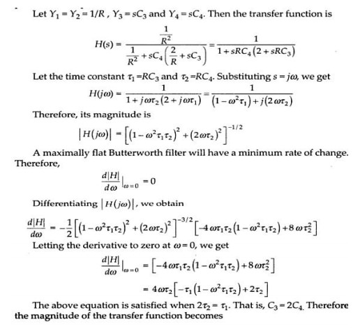
Second order LP Butterworth filter:
A
second order LPF having a gain 40dB/decade in stop band. A First order LPF can
be converted into a II order type simply by using an additional RC network.
The
gain of the II order filter is set by R1 and RF, while
the high cut off frequency fH is determined by R2, C2,
R3 and C3.
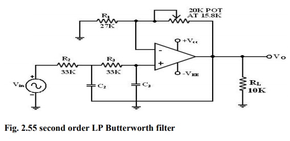
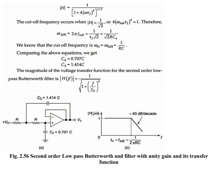
Filter Design:
1.
Choose a value for a high cut off freq. (fH ).
2.
To simplify the design calculations, set R2 = R3 = R and
C2 = C3 = C then choose a value of C<=1μf.
3. Calculate the value of R R =1/2πfhC
4.
Finally, because of the equal resistor (R2 = R3) and capacitor (C2 = C3
) values, the pass band volt gain AF = 1 + RF / R1
of the second order had to be = to 1.586. RF = 0.586 R1.
Hence choose a value of R1 <=100kΩ.
5. Calculate the value of RF.
First order HP Butterworth filter:
High
pass filters are often formed simply by interchanging frequency-determining
resistors and capacitors in low-pass filters.
(i.e)
I order HPF is formed from a I order LPF by interchanging components R & C.
Similarly II order HPF is formed from a II order LPF by interchanging R &
C.
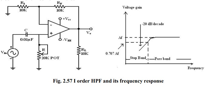
Here
I order HPF with a low cut off frequency of fL. This is the frequency at which
the magnitude of the gain is 0.707 times its passband value.
Here
all the frequencies higher than fL are passband frequencies.
The
output voltage V0 of the first order active high pass filter is
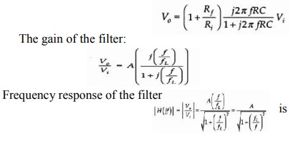
·
At
high frequencies f>fL gain = A.
·
At
f= fL gain = 0.707 A.
·
At
f < fL the gain decreases at a rate of -20 db /decade. The frequency below
cutoff frequency is stop band.
Second – order High Pass Butterworth Filter:
I
order Filter, II order HPF can be formed from a II order LPF by interchanging
the frequency
Related Topics