Precision diodes, Applications, Advantages, Disadvantage | Applications of Operational Amplifier - Precision Rectifier using Operational Amplifier | Linear Integrated Circuits : Applications of Operational Amplifier
Chapter: Linear Integrated Circuits : Applications of Operational Amplifier
Precision Rectifier using Operational Amplifier
Precision
Rectifier:
The
ordinary diodes cannot rectify voltages below the cut-in -voltage of the diode.
A circuit which can act as an ideal diode or precision signal – processing
rectifier circuit for rectifying voltages which are below the level of cut-in
voltage of the diode can be designed by placing the diode in the feedback loop
of an op-amp.
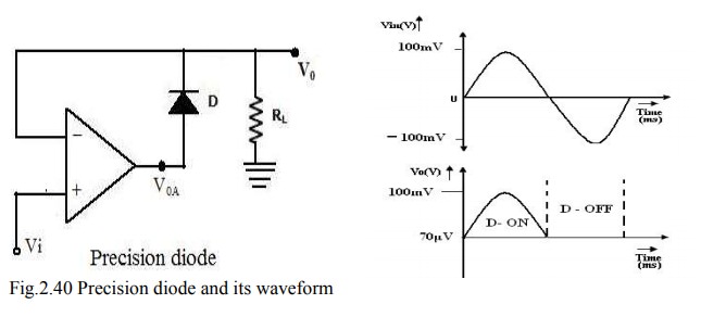
Precision diodes:
Figure
shows the arrangement of a precision diode. It is a single diode arrangement
and functions as a non-inverting precision half– wave rectifier circuit. If V1 in the circuit of figure is positive,
the op-amp output VOA also becomes positive. Then the closed loop
condition is achieved for the op-amp and the output voltage V0 = Vi
. When Vi < 0, the voltage V0A becomes negative and the diode is
reverse biased. The loop is then broken and the output V0 = 0.
Consider
the open loop gain AOL of the op-amp is approximately 104 and the
cut-in voltage Vγ for silicon diode is ≈ 0.7V. When the input voltage Vi >
Vγ / AOL, the output of the op-amp VOA exceeds Vγ and the diode D
conducts.
Then
the circuit acts like a voltage follower for input voltage level Vi > Vγ / AOL ,(i.e.
when Vi > 0.7/104 = 70μV), and the output voltage V0
follows the input voltage during the positive half cycle for input voltages
higher than 70μV as shown in figure.
When
Vi is negative or less than Vγ / AOL, the output of
op-amp VOA becomes negative, and the diode becomes reverse biased.
The loop is then broken, and the op-amp swings down to negative saturation.
However, the output terminal is now isolated from both the input signal and the
output of the op-amp terminal thus V0 =0.
No
current is then delivered to the load RL except for the small bias current of
the op-amp and the reverse saturation current of the diode.
This
circuit is an example of a non-linear circuit, in which linear operation is
achieved over the remaining region (Vi < 0). Since the output
swings to negative saturation level when Vi < 0, the circuit is
basically of saturating form. Thus the frequency response is also limited.
Applications: The precision diodes are used in
·
half
wave rectifier,
·
Full-wave
rectifier,
·
peak
value detector,
·
Clipper
and clamper circuits.
Disadvantage:
It
can be observed that the precision diode as shown in figure operated in the
first quadrant with Vi > 0 and V0 > 0. The operation in third
quadrant can be achieved by connecting the diode in reverse direction.
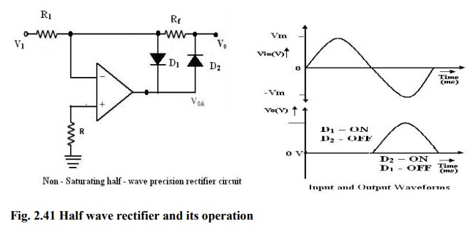
Half
– wave Rectifier:
A
non-saturating half wave precision rectifier circuit is shown in figure. When Vi
> 0V, the voltage at the inverting input becomes positive, forcing the
output VOA to go negative. This results in forward biasing the diode
D1 and the op-amp output drops only by ≈ 0.7V below the inverting
input voltage. Diode D2 becomes reverse biased. The output voltage V0
is zero when the input is positive.
When
Vi > 0, the op-amp output VOA becomes positive,
forward biasing the diode D2 and reverse biasing the diode D1.
The circuit then acts like an inverting amplifier circuit with a non-linear
diode in the forward path. The gain of the circuit is unity when Rf
= Ri.
The
circuit operation can mathematically be expressed as
V0
= 0 when Vi > 0 and
V0
= Rf/RiV1 forVi
< 0
The
voltage VoA at the op amp output is VOA = - 0.7V for Vi>0
VOA=
Rf/Ri V1 + 0.7V forVi<0
Advantages:
·
it
is a precision half wave rectifier and
·
it
is a non saturating one.
The
inverting characteristics of the output V0 can be circumvented by the use of an
additional inversion for achieving a positive output.
Full
wave Rectifier:
The
first part of the Full wave circuit is a half wave rectifier circuit. The
second part of the circuit is an inverting amplifier.
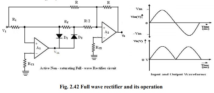
For
positive input voltage Vi > 0V and assuming that RF =Ri
= R, the output voltage VOA=Vi. The voltage V0
appears as (-) input to the summing op-amp circuit formed by A2, The
is R/(R/2), as shown in figure.
The
input Vi also appears as an input to the summing amplifier. Then, the net
output is V0=-Vi -2V0= -Vi -2(-Vi)
= Vi. Since Vi > 0V, V0 will be positive, with its
input output characteristics in first quadrant. For negative input Vi < 0V,
the output V‘0 of the first part of rectifier circuit is zero. Thus, one input
of the summing circuit has a value of zero. However, Vi is also applied as an
input to the summer circuit formed by the op-amp A2.
The
gain for this input id (-R/R) = -1, and hence the output is V0 =
-Vi. Since Vi is negative, V0 will be inverted and will thus be
positive. This corresponds to the second quadrant of the circuit.
To
summarize the operation of the circuit,
V0
= Vi when Vi < 0V and
V0
= Vi for Vi > 0V, and hence
V0
= |Vi |
Related Topics