Chapter: Linear Integrated Circuits : Analog Multiplier and PLL
Analog Multipliers
Analog
Multipliers:
A
multiple produces an output V0 which is proportional to the product of two
inputs Vx and Vy. V0 = KVxVy
where K is the scaling factor = (1/10) V-1.
There
are various methods available for performing analog multiplication. Four of
such techniques, namely,
1.
Logarithmic
summing technique
2.
Pulse
height/width modulation Technique
3.
Variable
trans conductance Technique
4.
Multiplication
using Gilbert cell and
5 Multiplication
using variable trans conductance technique.
An
actual multiplier has its output voltage V0 defined by
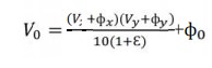
where
φx and φy are the offsets associated with signals Vx and Vy, ε is the error
signal associated with K and φ0 is the offset voltage of the multiplier output.
Terminologies associated voltage of the multiplier characteristics:
· Accuracy:
This
specifies the derivation of the actual output from the ideal output, for any
combination of X and Y inputs falling within the permissible operating range of
the multiplier.
· Linearity:
This
defines the accuracy of the multiplier. The Linearity Error can be defined as
the maximum absolute derivation of the error surface. This linearity error
imposes a lower limit on the multiplier accuracy.
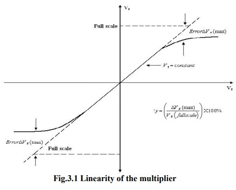
The
figure shows the response of the output as a function of one input voltage Vx
when the other Vy is assumed constant. It represents the maximum
percentage derivation from the ideal straight line output. An error surface is
formed by plotting the output for different combinations of X and Y inputs.
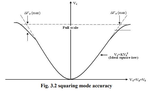
·
Square law accuracy:
The
Square – law curve is obtained with the X and Y inputs connected together and
applied with the same input signal. The maximum derivation of the output
voltage from an ideal square –law curve expresses the squaring mode accuracy.
· Bandwidth:
The
Bandwidth indicates the operating capability of an analog multiplier at higher
frequency values. Small signal 3 dB bandwidth defines the frequency f0 at which
the output reduces by 3dB from its low frequency value for a constant input
voltage. This is identified individually for the X and Y input channels
normally.
The
transconductance bandwidth represents the frequency at which the
transconductance of the multiplier drops by 3dB of its low frequency value.
This characteristic defines the application frequency ranges when used for
phase detection or AM detection.
·
Quadrant:
The
quadrant defines the applicability of the circuit for bipolar signals at its
inputs. First – quadrant device accepts only positive input signals, the two
quadrant device accepts one bipolar signal and one unipolar signal and the four
quadrant device accepts two bipolar signals.
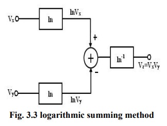
·
Logarithmic summing Technique:
This
technique uses the relationship ln Vx + lnVy =ln(VxVy)
As
shown in figure the input voltages Vx and Vy are
converted to their logarithmic equivalent, which are then added together by a
summer. An antilogarithmic converter produces the output voltage of the summer. The output is given by,
Vz
= ln-1(ln(Vx Vy )) = Vx Vy
.
The
relationship between I0 and VBE of the transistor is
given by IC = I0e(VBE /VT ) .It is found that the
transistor follows the relationship very accurately in the range of 10nA to
100mA. Logarithmic multiplier has low accuracy and high temperature
instability. This method is applicable only to positive values of Vx
and Vy.
Limitation: this type of multiplier is
restricted to one quadrant operation only.
·
Pulse Height/ Width Modulation
Technique:
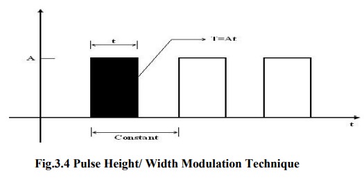
In
this method, the pulse width of a pulse train is made proportional to one input
voltage and the pulse amplitude is made proportional to the second input
voltage. Therefore, Vx =Kx A, Vy =Ky
t, and Vz =KzT where Kx, Ky, Kz
are scaling factors. In figure A is the amplitude of the pulse, t is the pulse
width and T is the area of=the pulse=. Therefore,
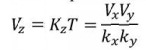
The
modulated pulse train is passed through an integrated circuit. Therefore, the
input of the integrator is proportional to the area of pulse, which in turn is
proportional to the product of two input voltages.
Related Topics