Phase Locked Loop - Control System Analysis/ Closed Loop Analysis of PLL | Linear Integrated Circuits : Analog Multiplier and PLL
Chapter: Linear Integrated Circuits : Analog Multiplier and PLL
Control System Analysis/ Closed Loop Analysis of PLL
Control
System Analysis/ Closed Loop Analysis of PLL
Phase
locked loops can also be analyzed as control systems by applying the Laplace
transform.
The
loop response can be written as:
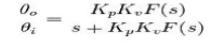
Where
·
θo is the output phase in radians
·
θi is the input phase in radians
·
Kp is the phase detector gain in volts
per radian
·
Kv is the VCO gain in radians per
volt-second
·
F(s) is the loop
filter transfer function (dimensionless)
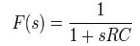
The
loop characteristics can be controlled by inserting different types of loop
filters. The simplest filter is a one-pole RC circuit. The loop transfer function
in this case is:
The
loop response becomes:
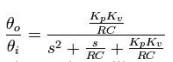
This
is the form of a classic harmonic oscillator. The denominator can be related to
that of a second order system:
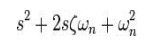
Where
ζ
is the damping factor
ωn is the natural frequency of the loop.
For
the one-pole RC filter,
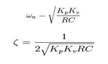
The
loop natural frequency is a measure of the response time of the loop, and the
damping factor is a measure of the overshoot and ringing. Ideally, the natural
frequency should be high and the damping factor should be near 0.707 (critical
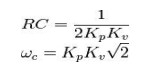
damping). With a single pole filter, it is not possible to control the loop
frequency and damping factor independently. For the case of critical damping,
A
slightly more effective filter, the lag-lead filter includes one pole and one
zero. This can be realized with two resistors and one capacitor. The transfer
function for this filter is
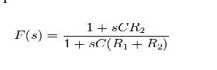
This
filter has two time constants
τ1
= C(R1 + R2) τ2
=CR2
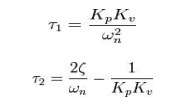
Substituting
above yields the following natural frequency and damping factor
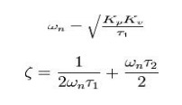
The
loop filter components can be calculated independently for a given natural
frequency and damping factor
Real
world loop filter design can be much more complex eg using higher order filters
to reduce various types or source of phase noise.
Applications of PLL:
The
PLL principle has been used in applications such as
·
FM
stereo decoders
·
motor
speed control
·
tracking
filters
·
FM
modulation and demodulation
·
FSK
modulation
·
Frequency
multiplier
·
Frequency
synthesis etc.,
Example
PLL ICs:560 series (560, 561, 562, 564, 565 & 567)
Related Topics