Chapter: Physics : Effects of electric current : Higher Secondary(12 Std)
Heating effect : Joule's law
Effects of electric current
The ideas of electric current, electromotive force having been already discussed in the preceding chapter, we shall discuss in this chapter the physical consequences of electric current. Living in an electrical and interestingly in an electronic age, we are familiar with many practical applications of electric current, such as bulbs, electroplating, electric fans, electric motors etc. In a source of emf, a part of the energy may go into useful work like in an electric motor. The remaining part of the energy is dissipated in the form of heat in the resistors. This is the heating effect of current. Just as current produces thermal energy, thermal energy may also be suitably used to produce an emf. This is thermoelectric effect. This effect is not only a cause but also a consequence of current. A steady electric current produces a magnetic field in surrounding space. This important physical consequence of current is magnetic effect of electric current.
Heating effect : Joule’s law
In a conductor, the free electrons are always at random motion making collisions with ions or atoms of the conductor. When a voltage V is applied between the ends of the conductor, resulting in the flow of current I, the free electrons are accelerated. Hence the electrons gain energy at the rate of VI per second. The lattice ions or atoms receive this energy VI from the colliding electrons in random bursts. This increase in energy is nothing but the thermal energy of the lattice. Thus for a steady current I, the amount of heat produced in time t is
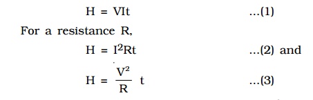
The above relations were experimentally verified by Joule and are known as Joule’s law of heating. By equation (2) Joule’s law implies that the heat produced is (i) directly proportional to the square of the current for a given R (ii) directly proportional to resistance R for a given I and (iii) directly proportional to the time of passage of current. Also by equation (3), the heat produced is inversely proportional to resistance R for a given V.
1.1Verification of Joule’s law
Joule’s law is verified using Joule’s calorimeter. It consists of a resistance coil R enclosed inside a copper calorimeter (Fig 3.1).
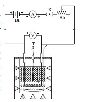
The ends of the coil are connected to two terminals, fixed to the lid of the calorimeter. A stirrer and a thermometer T are inserted through two holes in the lid. Two thirds of the volume of the calorimeter is filled with water. The calorimeter is enclosed in a wooden box to minimise loss of heat.
A battery (Bt), a key (K), a rheostat (Rh) and an ammeter (A) are connected in series with the calorimeter. A voltmeter (V) is connected across the ends of the coil R.
(i) Law of current
The initial temperature of water is measured as θ1. Let W be the heat capacity of the calorimeter and contents. Now a current of I1 is passed for a time of t (about 20 minutes). The final temperature (θ2) (after applying necessary correction) is noted. The quantity of heat gained by calorimeter and the contents is calculated as H1 = W (θ 2−θ1). Water is then cooled to θ1. The experiment is repeated by passing currents I2, I3 . . etc., through the same coil for the same interval of time t and the corresponding quantities of heat H2, H3 etc. are calculated. It is found that
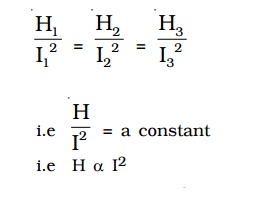
i.e. Hence, law of current is verified.
(ii) Law of resistance
The same amount of current I is passed for the same time t through different coils of resistances R1, R2, R3 etc. The corresponding quantities of heat gained H1, H2, H 3 etc. are calculated. It is found that,

(iii) Law of time
The same amount of current I is passed through the same resistance R for different intervals of time t1, t2, t3 etc. The corresponding quantities of heat gained H1, H2, H3 etc. are calculated. It is found that
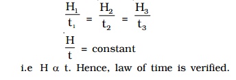
i.e H α t. Hence, law of time is verified.
2. Some applications of Joule heating
(i) Electric heating device
Electric iron, electric heater, electric toaster are some of the appliances that work on the principle of heating effect of current. In these appliances, Nichrome which is an alloy of nickel and chromium is used as the heating element for the following reasons.
1. It has high specific resistance
2. It has high melting point
3. It is not easily oxidized
(ii) Fuse wire
Fuse wire is an alloy of lead 37% and tin 63%. It is connected in series in an electric circuit. It has high resistance and low melting point. When large current flows through a circuit due to short circuiting, the fuse wire melts due to heating and hence the circuit becomes open. Therefore, the electric appliances are saved from damage.
(iii) Electric bulb
Since the resistance of the filament in the bulb is high, the quantity of heat produced is also high. Therefore, the filament is heated to incandescence and emits light. Tungsten with a high melting point (3380oC) is used as the filament. The filament is usually enclosed in a glass bulb containing some inert gas at low pressure.
Electric arc and electric welding also work on the principle of heating effect of current.
In some cases such as transformers and dynamos, Joule heating effect is undesirable. These devices are designed in such a way as to reduce the loss of energy due to heating.
3. Seebeck effect
In 1821, German Physicist Thomas Johann Seebeck discovered that in a circuit consisting of two dissimilar metals like iron and copper, an emf is developed when the junctions are maintained at different temperatures.
Two dissimilar metals connected to form two junctions is called thermocouple. The emf developed in the circuit is thermo electric emf. The current through the circuit is called thermoelectric current. This
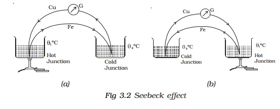
effect is called thermoelectric effect or Seebeck effect. If the hot and cold junctions are interchanged, the direction of current also reverses. Hence Seebeck effect is reversible. In a Cu-Fe thermocouple (Fig 3.2a), the direction of the current is from copper to iron at the hot junction (Fig 3.2b).
The magnitude and sign of thermo emf depends on the materials of the two conductors and the temperatures of the hot and cold junctions. Seebeck after studying the thermoelectric properties of different pairs of metals, arranged them in a series called thermoelectric series. The direction of the current at the hot junction is from the metal occurring earlier in the series to the one occurring later in the series. The magnitude of thermoemf is larger for metals appearing farther apart in the series. The thermo-electric series of metals is :
Bi, Ni, Pd, Pt, Cu, Mn, Hg, Pb, Sn, Au, Ag, Zn, Cd, Fe, Sb.
The position of the metal in the series depends upon the temperature. The thermoemf of any thermocouple has the temperature dependence given by the relation,
V = α θ + ½ β θ2,
where θ is the temperature difference between the junctions and α and β are constants depending on the nature of the materials.
4. Neutral and Inversion temperature
The graph showing the variation of thermoemf with temperature of the hot junction, taking the temperature of the cold junction (θC) as origin is shown in Fig 3.3. For small difference in temperature between the junctions, the graph is a straight line. For large difference in temperature, the graph is a parabola.
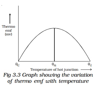
Keeping the temperature of the cold junction constant, the temperature of the hot junction is gradually increased. The thermo emf rises to a maximum at a temperature (θn) called neutral temperature and then gradually decreases and eventually becomes zero at a particular temperature (θi) called temperature of inversion. Beyond the temperature of inversion, the thermoemf changes sign and then increases.
For a given thermocouple, the neutral temperature is a constant, but the temperature of inversion depends upon the temperature of cold junction. These temperatures are related by the expression
5.Peltier effect
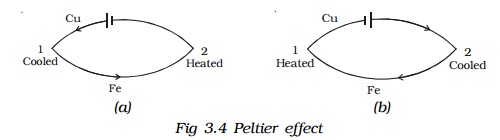
In 1834, a French scientist Peltier discovered that when electric current is passed through a circuit consisting of two dissimilar metals, heat is evolved at one junction and absorbed at the other junction. This is called Peltier effect. Peltier effect is the converse of Seebeck effect.
In a Cu-Fe thermocouple, at the junction 1 (Fig 3.4a) where the current flows from Cu to Fe, heat is absorbed (so, it gets cooled) and at the junction 2 where the current flows from Fe to Cu heat is liberated (so, it gets heated). When the direction of the current is reversed (Fig 3.4b) junction 1 gets heated and the junction 2 gets cooled. Hence Peltier effect is reversible.
Peltier Co-efficient (π)
The amount of heat energy absorbed or evolved at one of the junctions of a thermocouple when one ampere current flows for one second (one coulomb) is called Peltier coefficient. It is denoted by π. Its unit is volt. If H is the quantity of heat absorbed or evolved at one junction then H = π It
The Peltier coefficient at a junction is the Peltier emf at that junction. The Peltier coefficient depends on the pair of metals in contact and the temperature of the junction.
6. `Thomson effect
Thomson suggested that when a current flows through unequally heated conductors, heat energy is absorbed or evolved throughout the body of the metal.
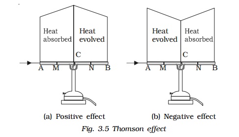
Consider a copper bar AB heated in the middle at the point C and current flowing as shown in Fig. 3.5a. When no current is flowing, the point M and N equidistant from C are at the same temperature. When current is passed from A to B. N shows higher temperature compared to M. Similarly, B will show higher temperature as compared to A. It means from A to C heat is absorbed and from C to B heat is evolved. This is known as positive Thomson effect. Similar effect is observed in the case of Sb, Ag, Zn, Cd, etc. When the current is passed from B to A, M will show higher temperature as compared to N.
In the case of Iron (fig. 3.5b), when it is heated at the point C and current is flowing from A to B, M shows higher temperature as compared to N. It means from A to C, heat is evolved and from C to B heat is absorbed. This is negative Thomson effect. Similar effect is observed in the case of Pt, Bi, Co, Ni, Hg, etc.
If we take a bar of lead and heat it at the middle point C, the point M and N equidistant from C show the same temperature when current is flowing from A to B or from B to A. Therefore, in the case of lead, Thomson effect is nil. Due to this reason, lead is used as one of the metals to form a thermo couple with other metals for the purpose of drawing thermo electric diagrams.
Thomson coefficient (σ)
The amount of heat energy absorbed or evolved when one ampere current flows for one second (one coulomb) in a metal between two points which differ in temperature by 1oC is called Thomson coefficient. It is denoted by σ. Its unit is volt per oC.
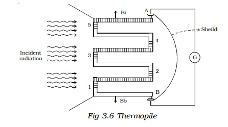
7. Thermopile
Thermopile is a device used to detect thermal radiation. It works on the principle of Seebeck effect.
Since a single thermocouple gives a very small emf, a large number of thermocouples are connected in series. The ends are connected to a galvanometer G (Fig. 3.6). One set of junctions (1,3,5) is blackened to absorb completely the thermal radiation falling on it. The other set of junctions (2,4) called cold junction is shielded from the radiation.
When thermal radiation falls on one set of junctions (1, 3, 5) a difference in temperature between the junctions is created and a large thermo emf is produced. The deflection in the galvanometer is proportional to the intensity of radiation.
Related Topics