Chapter: Aquaculture Engineering : Sea Cages
Calculation of current, wave and wind forces on a sea cage farm
Calculation of forces on a sea cage farm
To be able to design a cage with its mooring system, it is necessary to calculate the environmental forces affecting the farm. On ordinary sites it will be the current that causes the highest forces, while on more exposed sites the wave forces will also be considerable. The direct wind forces will be low due to the small area above the water. Both static and dynamic (from the waves) forces will affect the cages. The size of the forces must be known to find whether the cage construction will tolerate the forces on the site, or if the construction will break down. The supplier of the cage ought to have done these calculations and know whether the equipment will tolerate the forces at the site. However, the environmental forces will also determine the size and design of the mooring system, and these must be determined on site, because the environ-mental loads will vary with the site.
Calculation of the forces that affect the sea cages is quite difficult, especially for open ocean cages; normally computer programs utilizing numerical methods are employed (for the latest information see, for example, refs 28–30). In this section only a brief overview is presented, focusing on simplified solutions to increase the reader’s knowledge of how environmental forces affect floating constructions.
Types of force
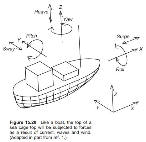
A construction floating in the water, for instance a boat or a sea cage, will be exposed to forces as a result of current, waves and wind. The forces can be resolved into three linear components in the x, y and z directions; the torque occurs around the same three axes (Fig 15.20):1
· Linear movements
heave: vertical motion
surge: horizontal motion along longitudinal axis
sway: horizontal motion along the transverse axis
· Rotating movements
yaw: rotation about the vertical axis
roll: rotation about the longitudinal axis
pitch: rotation about the transverse axis.
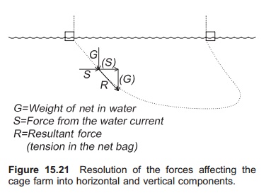
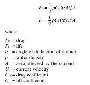
When doing calculations, the six forces may be resolved into two forces: a resultant horizontal force and a resultant vertical force. Even if the accuracy is less, the calculation is greatly simplified. Thus there are two forces affecting the farm (Fig. 15.21):
1. Drag force parallel with the current direction, FD
2. Lift force normal to the current direction, FL.
To give some idea of the environmental forces involved, the following minimum values have been recommended in Norway26 when designing a mooring system for sheltered offshore farms:
· Significant wave height: 1.5 m
· Current velocity: 1 m/s
· Wind: 30 m/s over 10 min period
· Storm flood tide: 1 m
· Fouling: 30% of the area underwater is fouled completely.
These values will, however, vary from site to site around the world, depending of the location. During the past few years an increasing number of exposed sites have been used for farming purposes where environmental forces are greater than those given above.
Calculation of current forces
General methods
All parts of a cage farm below the water surface will be affected by the current. This includes the net bag, the cage collar (pontoons), the buoys and the mooring lines. The size of the forces on the elements depends on the area affected by the current. Thus the net bag is affected the most because it has the largest area.
To calculate the current forces affecting a sub-merged construction, the first part of Morrison’s equation can be used. The same equation may also be used to calculate the wave forces, but here an acceleration term is also included. As the current velocity is constant, this term can be neglected when calculating the forces.
Morrison’s equation without the acceleration term and with forces only in the x direction can be written as follows:
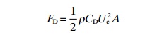
where:
FD=drag
ρ = water density
A = area affected by the current
Uc=current velocity
CD=drag coefficient.
The drag coefficient gives a picture of the current resistance between the object and the water current and is determined by experiment. If the object is square the coefficient will be higher than for an aerodynamically shaped construction. The drag coefficient can be found from the bar diameter and bar length of the net used in the cage bag. It can also be found from the solidity, Reynolds number and the angle of attack of the current.
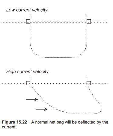
Fouling on the net bag will increase the current forces because the area of the net is increased, and by this the area that effects the current. Solidity increases with fouling because the bar diameter increases. To calculate the current forces on the net bag is, however, not easy. Not only does the water pass through the net bag, but the current will also cause the net bag to deflect (Fig. 15.22). By having several net bags one behind another, the current velocity will be reduced from net panel to net panel as a result of the resistance to flow through the net bags; therefore more and more water will gradually flow below and around the bags behind the first one.
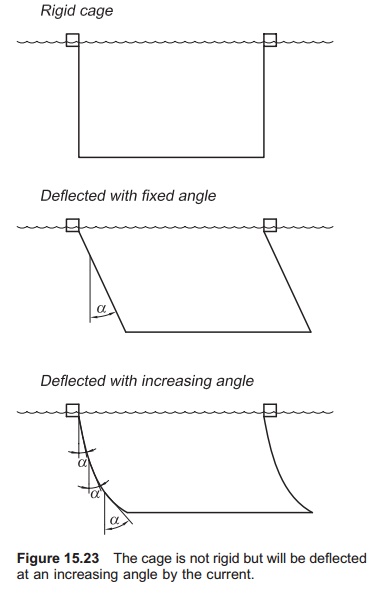
The net bag will be exposed to a lifting force due to the deflection because it is fixed on the surface by the mooring system. More accurate equations for the current forces affecting the net bags which are not rigid, and deflected by an angle a, will there-fore be as follows:
These equations will also only be partly correct because the net bag is not deflected by a fixed angle towards the surface, but in a curve (Fig. 15.23). By dividing the bag into several sections with different angles it is possible to compute the drag and the lift, but this requires a lot of calculations. The coefficients will depend mainly on the solidity of the net and the attack angle.
Because it is fairly complicated to calculate the forces on the entire net bag in one go, a method which divides the net bag into single net panels has been utilized. For example, a square cage contains four side panels and one bottom panel. The force is then calculated for each panel and the total force represents the sum of the forces on the separate panels: a trial showed that the calculated forces were in the range 0.9–1.3 of the measured forces.
The amount by which the net is deflected depends on the current velocity, the weights in the bottom of the bag, and the bag design. Experiments have shown that the reduction in volume of the net bag can be over 90%, when the velocity is increased from 0 to 1 m/s.To reduce the deformation, increased lump weights in the bottom could be used. However, this will increase the horizontal force on the net several times over and may not be advisable.33 In addition, if there are waves extra weights in the bottom of the bag will increase the wave loads on the net bag.
Reduction in velocity
When the water current passes one net panel the current velocity will be reduced by friction from the net; much of the water is then forced to go under and around the following nets. When the water current hits the next panel, the force on this panel will be reduced because the water velocity is reduced. To be able to calculate the forces on the following net panels it is necessary to know the size of this reduction, particularly since the velocity is squared in Morrison’s force equation so gives a large contribution.
The following equation may be used to estimate the current velocity Ui after i net panels:
Ui= Ucri
where:
i = number of net panels that the water has topass
Uc=current velocity of the water when it hits thefirst panel
r = reduction factor (depending on the solidity,Sn, for the net).
The velocity reduction factor may also be expressed by the drag coefficient CD, which again is affected by the solidity, Sn:
r =1−0.46CD
If Sn is between 0.1 and 0.35 CD may be calculated as follows:
CD=0.04+(−0.04+ Sn−1.24Sn2+13.7Sn3)cosa
where:
α = angle of deflection of the net.
If using rigid cage bags the equation will be as follows:
CD= Sn−1.24Sn2+13.7Sn3
As seen there is a dramatic reduction in velocity for every net panel the water has to pass.
In addition, to reduce the forces on the net bags that lie behind the first one will result in a reduction in supply of new oxygen-rich water. When having several cages, one after another in the direction of the current, lack of oxygen might occur in the last cages that the water passes. As the water exchange is reduced there will also be a reduction in removal of metabolic waste substances, which also shows the importance of correct individual placing of the cages in relation to the current direction.
By increasing amount of fouling the current velocity will be reduced even more, as a result of increased solidity, so it is important to minimize fouling on the nets.
Example
Three cages are lying behind each other. The velocity of the current that hits the first net panel is 0.7 m/s; CDis 0.32. Calculate the current velocity in each ofthe three cages assuming rigid nets.
First the velocity reduction factor (r) is calculated from CD
r =1−0.46(0.32)
=1 − 0.15
=0.85
Then the velocity inside cage 1 (after 1 net panel), cage 2 (after 3 net panels) and cage 3 (after 5 net panels)is calculated:
U1=0.7×0.851= 0.6 m/s
U2=0.7×0.853= 0.43 m/s
U3=0.7×0.855= 0.31 m/s
Simple method for calculating the current forces with rigid nets
As shown, there is a lot to consider when calculating the current forces on sea cages, and usually specially designed computer programs are used for this purpose. For rigid nets, however, it is possible to calculate the forces employing quite simple methods. Use of rigid nets will, however, result in overestimation of the forces compared to the real situation, but will show the principles. Using the values obtained to calculate the size of mooring lines and anchors will also ensure that the mooring is large enough, although the mooring system will be more expensive than necessary because it is over-specified.
A simple set of equations and diagrams have been developed for calculation of the current forces on rigid sea cages.33The method assumes rigid mesh/bags with no deflection, so therefore no lifting forces. In addition, only forces normal and parallel to the current on the farm are taken into consideration.
First the drag on the net panel normal to the current direction, FDN, must be calculated; then forces parallel to the current direction FDP are calculated; these are then added to give the total forces FDtot
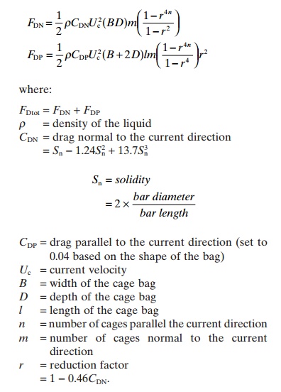
The above equation is used to find the force when the farm is parallel to the current direction. To useit when the farm is normal to the current direction requires only that the values of n and m in the equations be exchanged.
Example
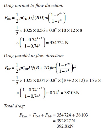
A rectangular system farm includes two cage bags, one after another and eight side by side in relation to main current direction, a total of 16 cages. The size of the single cage is: width 10 m, length 15 m, depth 12 m. The design water flow is 0.8 m/s. Calculate the current forces that affect the farm, presuming rigid nets.
The drag coefficient CDN must be calculated first:
CDN= Sn−1.24Sn2+13.7Sn3
=0.3 − 1.24 × 0.32+ 13.7 × 0.33
=0.56
Calculate r
r =1−0.46CDN = 0.74
Then the forces on the net panels normal (FDN)on parallel (FDP) with the current direction can be calculated.
Another very simple method is to use Morrison’s equation on the total length of the rope used to create the net panel. By calculating the current resistance from the total length of the rope the total forces affecting the bag can be found.
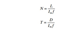
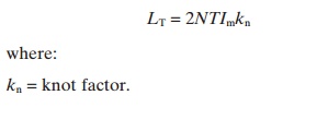
where:
N =number of meshes in the length of the panel
Im=bar length
f =coefficient of decrease (normally around 0.7)
L =length of the panel
T =number of meshes in the depth of the panel
D =depth of the panel.
Next the length of the filament (rope) per side (LT) is calculated:
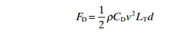
Therefore the total drag force on the net panel can be calculated by Morrisons equation:
where:
d = rope diameter (bar diameter)
CD=drag coefficient for a cylinder is used since this is the same as that of the rope, and this is 1.2.
Calculation of wave forces
Waves are important when designing sea cages. The wave forces will influence design of both the cage collars and the net bag. If the wave forces are too high the collar may break. The wave forces will, however, also affect the mooring systems and must be taken into consideration when calculating the size of the mooring system, even if they are smaller than the current forces.
Calculation of wave forces normally involves the use of computer programs and numeric solutions. Methods for calculating the wave forces include, for instance, Morrison’s equation, diffraction theory and Froude–Krylov forces.7,12 Calculations for traditional fixed offshore constructions will over estimate the forces for a pre-stressed cage farm floating on the surface and following the sea.
Compared to currents waves apply dynamic forces to the construction. Use of Morrison’s equation can illustrate this. Morrison’s equation has two additional terms, one for the velocity of the water particle in the wave and one for the acceleration of the water particle:
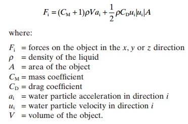
Without going deeper into this equation, it shows that in addition to the drag term, as there was for current forces, there is a mass force term that is proportional to the acceleration. The total force is the sum of these two forces.
Wave forces are dynamic, which means that they come again and again. This will result in reduced loads being tolerated by structures before breakage occurs. Experiments have shown that a cage may only tolerate a dynamic load which is 10% of one single static load.5 Waves impose additional forces on the mooring system. On normal, partly protected off-shore sites, the wave forces will be much lower than the current forces. Usually waves add up to 20–30% to the current forces, but this is of course site-dependent.
Due to the complexity of calculating wave forces and measuring water particle velocity and acceleration, this will not be further described here. Specialized literature is recommended, as mentioned earlier.
Calculation of wind forces
Since such a small part of a cage farm is above the water surface where the wind is blowing, the forces transferred to the cage and further to the mooring system will be very low compared to the forces from the current. To calculate the forces on the jumping net the following equation may be used:
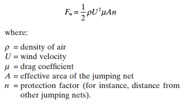
The wind forces will be considerably higher if, for instance, a feed barge is moored together with the cages.
Related Topics