Chapter: Civil : Principles of Solid Mechanics : Strain and Stress
The Stress Tensor
The Stress
Tensor
The concept of force
coming directly from physical observation of deforma-tion was first quantified
in one dimension by Hooke but intuitively recog-nized by cavemen. To
generalize to 3D and introduce the concept of internal force per unit
area (stress), requires the idea of equilibrium and the limit pro-cess of
calculus.
Consider again the
standard 3D structural blob in equilibrium from external boundary forces and
slice it to expose a plane defined by its normal vector n (Figure 2.3a).
For equilibrium of the remaining piece, there must be a result-ant force and/or
couple acting on the cross-section of area A. If they can be calculated
from any slice from the six equilibrium equations (in 3D), the structure is
statically determinate for internal forces and shear, bending moment, torque,
and normal force diagrams can be drawn. However, what the cross-section
actually feels is small increments of force Vector ?Fi at
various ori-entations distributed in some undetermined (and usually
difficult-to-determine) way. It is this distribution of force and moment over
the area (the stress field) that we hope to discover (stress analysis) and, if
we are clever, then change and control (design). As we shall see, this stress
distribution is almost never determinate.**
![]()
For now let n be in the x
direction so that the exposed surface is a yz plane. Over a small
area ?Ax = ?y?z surrounding any point 0, there
will be a force Vector ?F
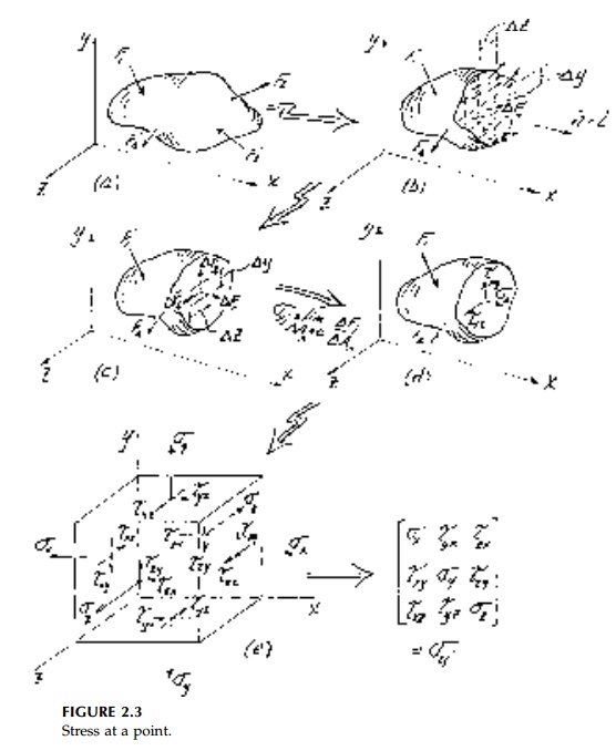
(inclined at an
arbitrary angle) with components ?Fxx ?Fxy ?Fxz
(Figure 2.3c). The first subscript identifies the plane on which the force acts
defined by the direction of its normal, in this case x, and the second
the direction of the force component itself. Positive components are those
(Figure 2.3e) with both sub-scripts positive or negative.
The average 'intensity of force' or
average stress is defined as the ratio ?F/ ?A analogous to
'average strain' dij for finite linear displacement.
Taking the limit as ?Ax ? 0, gives x stresses at O
(Figure 2.3d). As with strains, the shear components are highlighted by using a
different symbol in engineering notation to emphasize the physical difference
between normal and in-plane components of stress.
If we now slice the structure parallel
to the xy and xz planes through 0, then, by analogy, we find that
the complete state of stress is defined by 9 compo-nents (3 vectors) given by:

as shown in Figure 2.3 e. Shortly we
will show that the stress tensor is, in fact, 'naturally' symmetric in that the
three moment equilibrium equations for a differential element reduce to:

Thus, only six vector components are
actually involved in defining a state of stress at a point.
Related Topics