Chapter: Civil : Principles of Solid Mechanics : Strain and Stress
Mohr's Circle in Three Dimensions
Mohr's Circle in
Three Dimensions
Mohr's circle can be
extended to represent three-dimensional symmetric ten-sors such as stress.
Unfortunately it is incomplete in that it can only be con-structed in principal
space and even then requires an auxiliary construction (or calculation) to
decompose the shear stress resultant. Nevertheless the 3D Mohr's Circle is very
useful to portray limiting cases, and particularly the invariants which, as we
have seen, appear as stress components (or result-ants) themselves on the
octahedral planes.
Referring to Figure 2.10a, once the
principal values have been found from the characteristic Equation (2.14), three
2D circles representing each principal plane
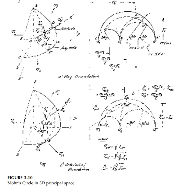
can be drawn defining
the tensor in principal space. Since the principal values are limit values, all
other orientations for the tensor must be in the area between these circles
(shown slashed).*
There are many ways to
then locate a point (say point P) in this principal space, which
represents a new orientation of axes. The transformation equations use the
direction cosines, but point P can be described more graphically using
just two angles: latitude, ?, and longitude, ?, as shown in Figure 2.10a. As we
have already seen in 2D, these will be mapped as double angles. Circle BPF of
longitude is a 'great circle' (center at 0) so its center must lie along the ?
(or E)
axis and arc B'F' can be drawn. While circle DPE of latitude is not a great circle,
all circles of latitude must have their centers along the same line as the
equator AFC at s1 2 s3 / 2 in
stress space.
That is, circles of latitude are only seen as circles when looking down the ?2
axis. Thus, again by trial-and-error, arc E'D'
can be drawn locating, point P'
uniquely in the ? -? (or E-?2)
space to determine the normal and shear-resultant components normal and
tangential to the new orientation x'.
The octahedral orientation along the space diagonal for the same set of stress
is shown in Figure 2.10b. Also shown is the maximum shear stress orientation
which, in principal space, is actually the quadrahedral state in the 1-3 plane.
There are corresponding 1-2 and 2-3 states which are intermediate quadrahedral
orientations.
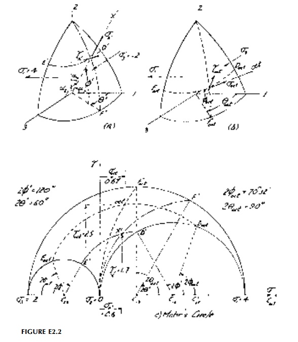
Example 2.2
For the state of stress
of Example 2.1 (?1 = 4ksi, ?2
=
0, ?3 = -2ksi),
determine using Mohr's Circle (and check by formula)
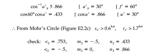
(a) the
normal and total shear stress on an x'
face given by direction cosines l1
=
0.433, m1 = 0.866, n1
=
0.25 and
(b) the
octahedral orientation.
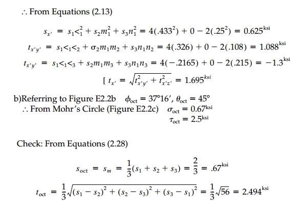
(a)Referring to Figure E2.2a:
From
Equations (2.13)
Related Topics