Chapter: Civil : Principles of Solid Mechanics : Strain and Stress
The Strain Tensor
The Strain
Tensor
As on a finite scale, the deformation
tensor can be 'dissolved' into its sym-metric and asymmetric components:
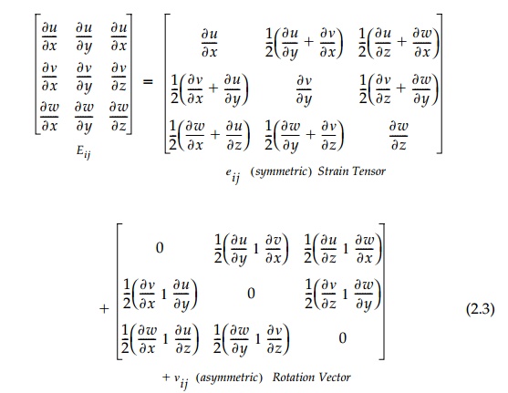
each of which produces a 'deformation' of the orthogonal differential baselengths dx, dy, and dz, exactly like its counterpart in the symmetric dis-placement tensor dij with respect to finite base lengths x, y, and z when u, v, and w are linear functions. Physically, the diagonal terms are unfortunate original definition (by Navier and Cauchy in 1821) of shear ? as the sum of counteracting angle changes rather than their average is historically significant in that much of the important literature has used it.
The off-diagonal terms,
? ij = total counteracting
angle change between othogonal baselengths (in the i and j
directions) and are positive when they increase d? (Bar).
![]()
The same symbol is even used for the
rotation of the differential element where the vector components of ?ij
are defined as:
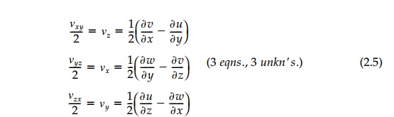
positive by the
'right-hand-screw-rule' as in Chapter 1 for finite baselengths. A complete
drawing of the deformation of a 3D differential element showing each vector
component of strain and rotation adding to give the total deriva-tive is
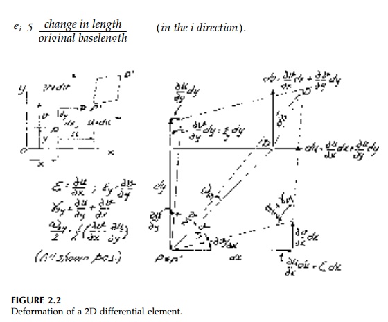
complicated.* The 2D (in-plane) drawing, Figure 2.2, illustrating the basic
definitions for ?x, ?y, ?xy,
and ?xy is more easily understood.
Generally at this point in the development
of the 'theory of elasticity,' at least in its basic form, these elastic
rotations as defined by Equation (2.5) are termed 'rigid body' and thereafter
dismissed. This is a conceptual mistake and we will not disregard the
rotational component of Eij.
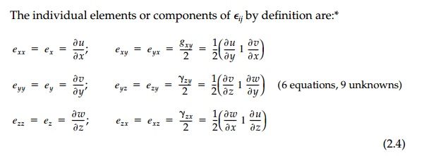
Equation (2.4) represents 6 field
equations relating the displacement vec-tor field with 3 unknown components to
the strain-tensor field with 6 unknown components. With the rotation field we
have 3 more equations and unknowns. Since 9 deformation components are defined
in terms of 3 displacements, the strains and rotations cannot be taken
arbitrarily, but must be related by the so-called compatibility relationships
usually given in the form:
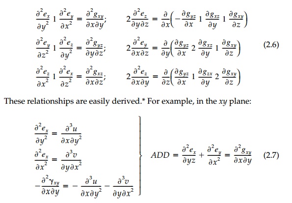
and the first compatibility relationship
(for the 2D) case is obtained. Three further compatibility relationships can be
found if the rotations are used instead of the shears. For example, in the 2D
case (x,y plane) using
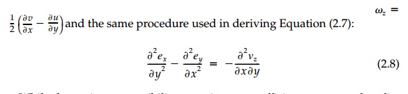
and the same procedure used in deriving
Equation (2.7):
While these nine compatibility equations
are sufficient to ensure that dis-placement functions u, v, and w
will be smooth and continuous, they are never sufficient in themselves to solve
for displacements. Thus all structures are 'geometrically indeterminate' and we
must investigate the stress field describing the flow of forces from the
boundary to the supports in order to develop additional equations to work with.
The tacit 'assumption' of Hooke's law validated over years of observation, is
that the deformation field (strains and rotations) are caused by stresses (or
vice versa) and the two can be related by material properties determined in the
laboratory.
Related Topics