Chapter: Electrical machines : Synchronous Generator
Synchronous Generators
Synchronous Generators
Synchronous machines are principally used as alternating current (AC) generators.
- They supply the electric power used by all sectors of modern societies: industrial, commercial, agricultural, and domestic. They
- usually operate together (or in parallel), forming a large power system supplying electrical energy to the loads or consumers.
- are built in large units, their rating ranging from tens to hundreds of megawatts.
- converts mechanical power to ac electric power. The source of mechanical power, the prime mover, may be a diesel engine, a steam turbine, a water turbine, or any similar device.
For high-speed machines, the prime movers are usually steam turbines employing fossil or nuclear energy resources.
Low-speed machines are often driven by hydro-turbines that employ water power for generation.
Smaller synchronous machines are sometimes used for private generation and as standby units, with diesel engines or gas turbines as prime movers.
1. Various Types of Synchronous Machine & Construction
According to the arrangement of the field and armature windings, synchronous machines may be classified as rotating-armature type or rotating-field type.
2. Rotating-Armature Type:
The armature winding is on the rotor and the field system is on the stator.
3. Rotating-Field Type:
The armature winding is on the stator and the field system is on the rotor.
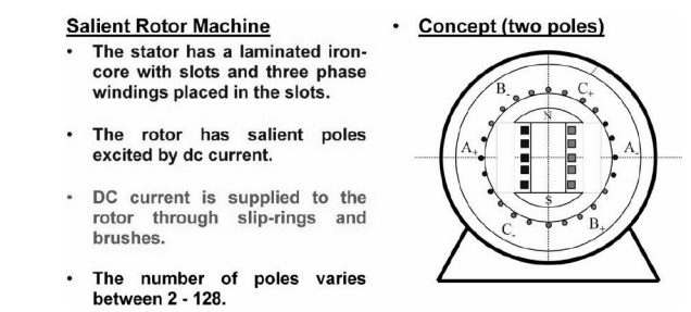
According to the shape of the field, synchronous machines may be classified as cylindrical-rotor (non-salient pole) machines andsalient-pole machines
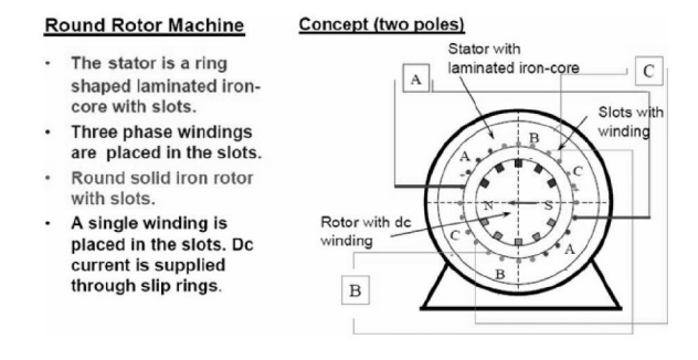
AC winding design
The windings used in rotating electrical machines can be classified as
Concentrated Windings
• All the winding turns are wound together in series to form one multi-turn coil
• All the turns have the same magnetic axis
• Examples of concentrated winding are
- field windings for salient-pole synchronous machines
- D.C. machines
- Primary and secondary windings of a transformer
Distributed Windings
• All the winding turns are arranged in several full-pitch or fractional-pitch coils
• These coils are then housed in the slots spread around the air-gap periphery to form phase or commutator winding
• Examples of distributed winding are
- Stator and rotor of induction machines
- The armatures of both synchronous and D.C. machines
Some of the terms common to armature windings are described below:
Conductor. A length of wire which takes active part in the energy- conversion process is a called a conductor.
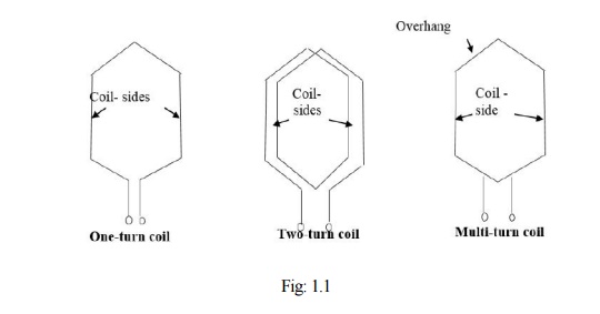
Turn. One turn consists of two conductors.
Coil. One coil may consist of any number of turns.
Coil -side. One coil with any number of turns has two coil-sides.
The number of conductors (C) in any coil-side is equal to the number of turns (N) in that coil.
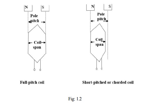
Pole - pitch:- A pole pitch is defined as the peripheral distance between identical points on two adjacent poles. Pole pitch is always equal to 180o electrical.
Coil-span or coil-pitch:- The distance between the two coil-sides of a coil is called coil-span or coil-pitch. It is usually measured in terms of teeth, slots or electrical degrees.
Chorded-coil
- If the coil-span (or coil-pitch) is equal to the pole-pitch, then the coil is termed a full-pitch coil.
- in case the coil-pitch is less than pole-pitch, then it is called chorded, short-pitch or fractional-pitch coil
Fractional-pitch coil
In AC armature windings, the separate coils may be connected in several different manners, but the two most common methods arelap and wave.
Cylindrical Rotor Theory
Similar to the case of DC generator, the behavior of a Synchronous generator connected to an external load is different than that at no-load. In order to understand the performance of the Synchronous generator when it is loaded, consider the flux distributions in the machine when the armature also carries a current. Unlike in the DC machine in alternators the emf peak and the current peak will not occur in the same coil due to the effect of the power factor of the load. The current and the induced emf will be at their peaks in the same coil only for upf loads. For zero power factor lagging loads, the current reaches its peak in a coil which falls behind that coil wherein the induced emf is at its peak by 90 electrical degrees or half a pole-pitch. Likewise for zero power factor leading loads, the current reaches its peak in a coil which is ahead of that coil wherein the induced emf is at its peak by 90 electrical degrees or half a pole-pitch. For simplicity, assume the resistance and leakage reactance of the stator windings to be negligible. Also assume the magnetic circuit to be linear i.e. the flux in the magnetic circuit is deemed to be proportional to the resultant ampere-turns - in other words the machine is operating in the linear portion of the magnetization characteristics. Thus the emf induced is the same as the terminal voltage, and the phase-angle between current and emf is determined only by the power factor (pf) of the external load connected to the synchronous generator.
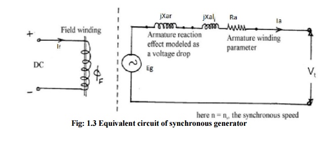
For synchronous generator the terminal voltage Vt can be written as
Where Eg is the generator induced emf,
Ia is the armature current,
Ra is the armature resistance,
Xal is the leakage reactance,
Xar is the armature reaction reactance,
Xs is the synchronous reactance
Zs is the synchronous impedance
Phasor Diagrams
The complete phasor diagram of an alternator at different load conditions are shown below.
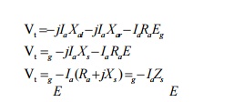
1. For Inductive Load
The alternator is connected with a R-L load then the current lags terminal voltage by an angle q. The phasor diagram is shown below in Fig: 1.4.
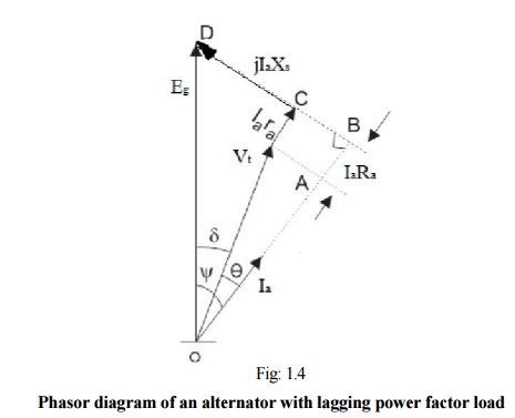
2. For Resistive Load
The alternator is connected with a resistive load then the current remains in same phase with the terminal voltage. The phasor diagram is shown below in Fig: 1.5.
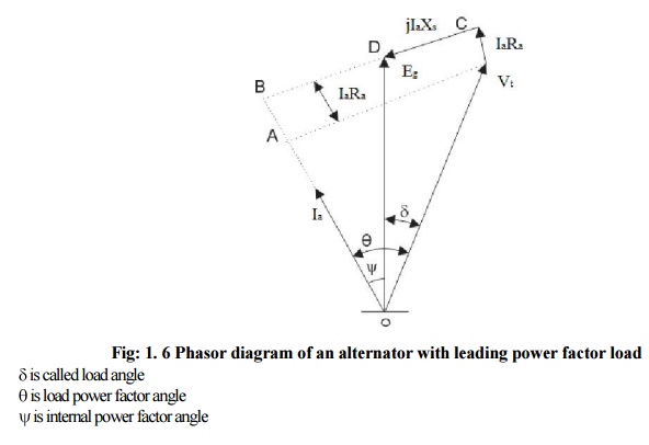
3. For Capacitive Load
When the terminals of the armature of alternator is connected with a R-C load then the current Ia leads the terminal voltage Vt by an angle . The complete phasor diagram for leading power factor load is shown below in Fig: 1. 6.
Related Topics