Chapter: Electrical machines : Synchronous Generator
Potier Reactance - Synchronous Generator
Potier Reactance
For
obtaining potier reactance Zero Power Factor test is conducted by connecting
the alternator to ZPF load and exciting the alternator in such way that the
alternator supplies the rated current at rated voltage running at rated speed.
To plot ZPF characteristics only two points are required. One point is
corresponding to the zero voltage and rated current that can be obtained from
scc and the other at rated voltage and rated current under zpf load. This zero
power factor curve appears like OCC
but shifted by a factor IaXL
vertically and horizontally by armature reaction mmf as shown below in Fig:
1.15. Following are the steps to draw ZPF characteristics.
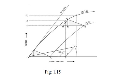
By
suitable tests plot OCC and SCC. Draw air gap line. Conduct ZPF test at full
load for rated voltage and fix the point B. Draw the line BH with length equal
to field current required to produce full load current on short circuit. Draw
HD parallel to the air gap line so as to cut the OCC. Draw DE perpendicular to
HB or parallel to voltage axis. Now, DE represents voltage drop IXL and BE represents the field current
required to overcome the effect of armature reaction.
Triangle
BDE is called Potier triangle and XL
is the Potier reactance.
Related Topics