Chapter: Electrical machines : Synchronous Generator
Slip Test
Slip Test
From this
test the values of Xd and Xq are determined by applying a
balance reduced external voltage (say, V volts, around 25% of rated value) to
the armature. The field winding remains unexcited. The machine is run at a
speed a little less than the synchronous speed (the slip being less than 1%)
using a prime mover (or motor). Connection diagram is shown in circuit diagram.

Due to
voltage V applied to the stator terminal a current I will flow causing a stator
mmf. This stator mmf moves slowly relative to the poles and induced an emf in
the field circuit in a similar fashion to that of rotor in an induction motor
at slip frequency. The effect will be that the stator mmf will moves slowly
relative to the poles.
The
physical poles and the armature-reaction mmf are alternately in phase and out,
the change occurring at slip frequency. When the axis of the pole and the axis
of the armature reaction mmf wave coincide, the armature mmf acts through the
field magnetic circuit. Since the applied voltage is constant, the air-gap flux
would be constant. When crest of the rotating armature mmf is in line with the
field-pole axis, minimum air-gap offers minimum reluctance thus the current
required in armature for the establishment of constant air-gap flux must be
minimum. Constant applied voltage minus the minimum impedance voltage drop in
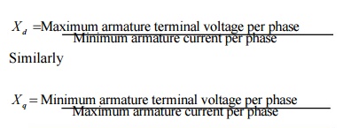
the armature terminal gives maximum armature terminal voltage. Thus the d-axis
synchronous reactance is given by

Related Topics