Chapter: Electrical machines : Synchronous Generator
Load Characteristics - Synchronous Generator
Load Characteristics
Consider a synchronous generator driven at constant speed and with constant excitation. On open circuit the terminal voltage Vt is the same as the open circuit e.m.f. Eg. Suppose a unity-power-factor load be connected to the machine. The flow of load current produces a voltage drop IaZs in the synchronous impedance, and terminal voltage Vt is reduced. Fig. 1.12 shows the phasor diagram for three types of load. It will be seen that the angle s between Eg and Vt increases with load, indicating a shift of the flux across the pole faces due to cross- magnetization. The terminal voltage is obtained from the complex summation
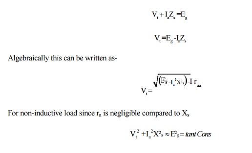
so that
the V/I curve, Fig. 1.13, is nearly an ellipse with semi-axes Eg and Isc.
The current Isc is that which flows when the load resistance is
reduced to zero. The voltage Vt falls to zero also and the machine
is on short-circuit with Vt = 0 and
Ia =Isc =Eg /Zs
~ Eg /Xs
For a
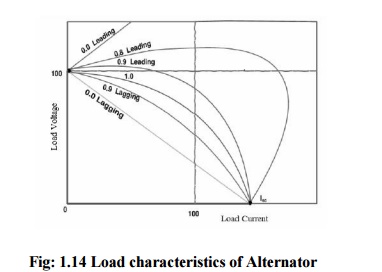
lagging load of zero power-factor, diagram is given in Fig. 1.13. The voltage
is given as before and since the resistance in normal machines is small
compared with the synchronous reactance, the voltage is given approximately by
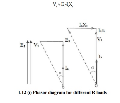
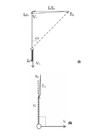
which is
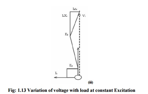
the straight line marked for cosϕ = 0 lagging in Fig.1.14. A leading load of zero
power factor Fig. 1.14 will have the voltage

another
straight line for which, by reason of the direct magnetizing effect of leading
currents, the voltage increases with load.
Intermediate
load power factors produce voltage/current characteristics resembling those in
Fig: 1.13 The voltage-drop with load (i.e. the regulation) is clearly dependent
upon the power factor of the load. The short-circuit current Isc at which the load terminal
voltage falls to zero may be about 150 per cent (1.5 per unit) of normal
current in large modern machines.
Related Topics